Documentation
Erae 2
20 chapters
Introduction
What is Erae 2?
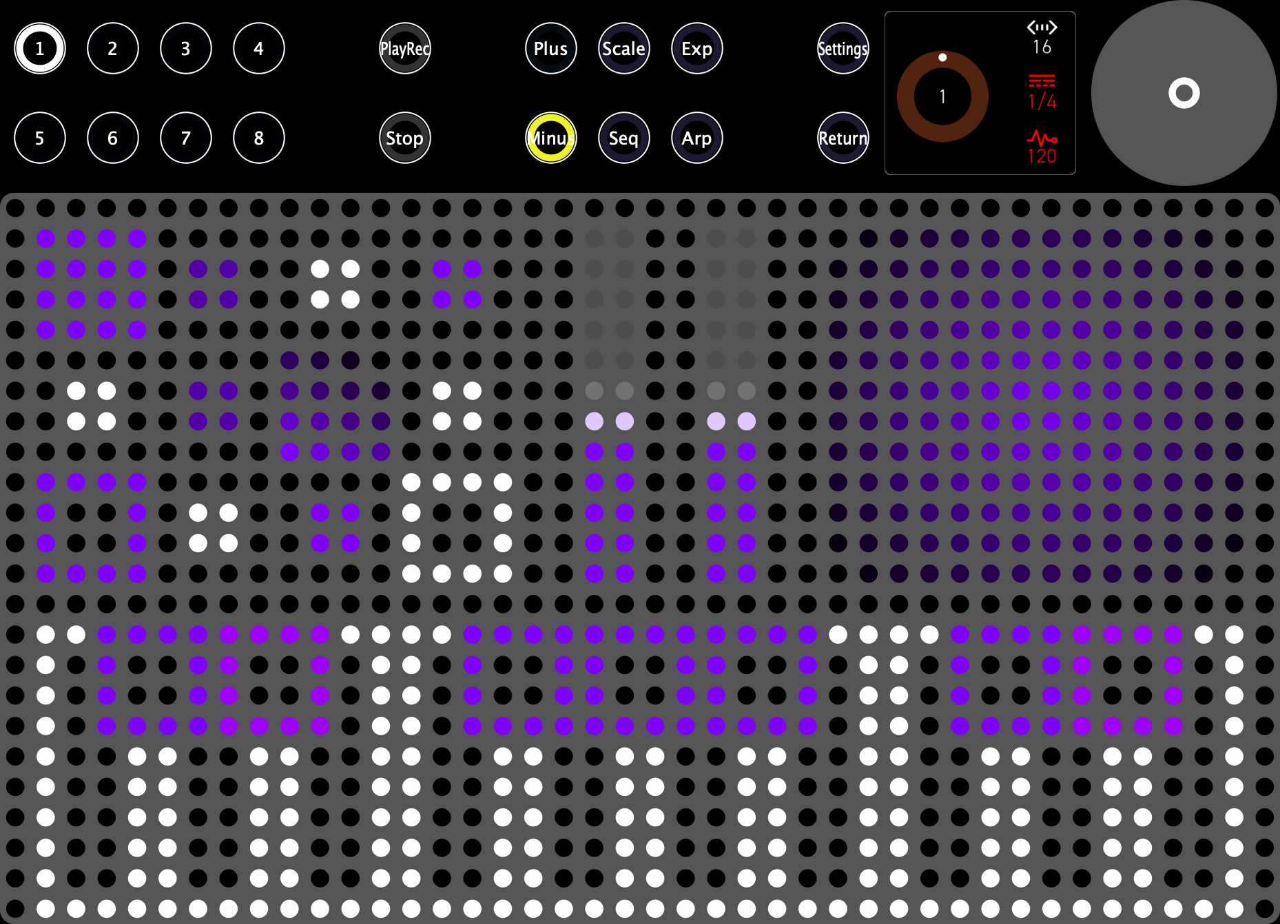
Erae 2 is a pressure-sensitive MIDI controller by Embodme. Its 42×24 LED grid is backed by a high-resolution Force-Sensitive Resistor matrix that captures X, Y, and Z (pressure) data from every finger simultaneously, turning the surface into a fully expressive instrument you design yourself. Whether you play it as a keyboard, a bank of faders, a live looper, or something in between, Erae 2 adapts to your workflow.
Erae 2 is built for musicians who want more than velocity. It speaks MPE, sends CV, runs a built-in arpeggiator and looper, and stores up to eight independent layouts -- all without a computer once configured.
Key Features
- 42×24 touch surface — 1,008 LED cells sit above a high-resolution FSR matrix with 16 raw sensing sites per LED cell, for more than 16,000 pressure-sensing locations across the full surface.
- XYZ expression per finger — pressure, horizontal slide, and vertical slide are tracked independently for every simultaneous touch, up to 16 fingers.
- 10 element types — Key, Button (Note, Control Change, Program Change, CV), Fader 1D, Fader 2D, Ableton Launchpad, API Zone, and Pedal.
- 8 layouts — store and switch between eight fully independent surface configurations on the device.
- MPE support — per-note pitch bend, pressure, and slide over MIDI Polyphonic Expression for expressive polyphonic play.
- CV outputs — 24 control voltage outputs for connecting to modular and analog synthesizers.
- LCD interface — a 280×240 colour display for browsing layouts, tuning elements, and navigating settings without a computer.
- Arpeggiator — a configurable arpeggiator that works across any key or button element in the active layout.
- Looper — a performance looper for capturing and overdubbing MIDI phrases in real time.
Tip: Erae 2 works standalone after configuration. Once your layouts are saved on the device, you do not need Erae Lab open during performance.
Who This Manual is For
This manual is written for musicians, producers, and experimenters who want to get the most out of Erae 2. It covers every aspect of the device — from placing your first element on a layout to routing CV to a modular rack. No prior experience with Erae 2 is required, but familiarity with basic MIDI concepts (channels, notes, control change) is helpful.
What's in the Box
- Erae 2 controller
- USB-C cable
- Quick-start card
Tip: Download Erae Lab from the Embodme website to design and manage layouts from your computer. Erae Lab is free and runs on macOS and Windows.
Manual Conventions
Throughout this manual:
- Parameter names appear in bold (e.g., Scale, Pressure Curve).
- Parameter values appear in
code formatting(e.g.,Chromatic,50%,MPE). - Tips appear as blockquotes like the ones in this chapter.
- Screenshots are indicated by captions above each image.
- Cross-references link to other chapters (e.g., Layouts) or to specific sections (e.g., CV Outputs).
- References to Erae Lab features are written as plain text: "See the Erae Lab User Manual, Chapter X."
Getting Started
This chapter walks you through powering on Erae 2, making your first connections, and playing your first layout — whether you are working with a DAW over USB or performing standalone without a computer.
Power On and Boot Sequence
Erae 2 is powered exclusively over USB-C. Connect the included USB-C cable from the USB Device port on the rear panel to a USB host (computer, powered hub, or USB power adapter). The device does not require a separate power supply.
On power-on, the following boot sequence occurs:
- The LED surface illuminates in a sweeping animation while the firmware initialises the touch hardware and loads your last-used project from the SD-backed project library when available, with flash backup/fallback behavior for recovery states.
- The LCD display shows the Embodme logo, then transitions to the Home screen once the system is ready.
- The menu buttons along the left edge of the surface light up, indicating normal operation.
The entire boot process takes approximately three to five seconds. The device is ready to play as soon as the Home screen appears.
Tip: If the LED surface remains dark after several seconds, check that the USB-C cable is fully seated and that the host port provides at least 500 mA. Bus-powered USB hubs may not supply enough current.
USB Connection (Class-Compliant MIDI)
Erae 2 appears as a class-compliant USB MIDI device — no driver installation is required on macOS, Windows 10/11, or Linux. Connect the USB Device port to your computer using a USB-C to USB-C or USB-C to USB-A cable.
In normal MIDI 1.0 mode, your DAW or MIDI software sees two user-facing USB MIDI ports:
| Cable | Port name | Purpose |
|---|---|---|
| Main (cable 0) | Erae 2 MIDI | Standard MIDI — note output for non-MPE instruments and general DAW use |
| MPE (cable 1) | Erae 2 MIDI (MPE) | Per-note expression for MPE-compatible instruments (e.g. Equator2, Pigments, Omnisphere) |
Select Erae 2 MIDI (Main) in your DAW's MIDI input preferences to receive note, velocity, pitch bend, and continuous controller messages from the surface. For MPE-capable instruments, point the instrument to Erae 2 MIDI (MPE) instead.
MIDI 2.0 is an alternate USB mode controlled by Settings > MIDI 2.0: ON/OFF and requires a reboot when changed. Most DAW users should leave MIDI 2.0 off unless instructed by Embodme or by a specific EraeSound/Erae Lab workflow.
Tip: On macOS, open Audio MIDI Setup -> MIDI Studio to confirm the device is enumerated correctly. If the device appears with a numbered suffix (e.g.
Erae 2 2) after a firmware update, open Audio MIDI Setup, select the old entry, and remove it. Reconnect USB to restore a clean enumeration.
TRS MIDI
Erae 2 includes a 3.5 mm TRS MIDI output and a combined TRS MIDI input on the rear panel, allowing connection to hardware synthesisers, drum machines, and effects units without a computer.
The TRS MIDI jack is switchable between Type A and Type B wiring in the Settings menu (Settings). Check the documentation of your target device to determine which type it expects:
- Type A — used by Arturia, MAKE NOISE, and many Eurorack modules.
- Type B — used by Korg, Teenage Engineering, and certain Roland devices.
Use a TRS-to-DIN adapter (included — two adapters ship in the box) to connect to standard 5-pin DIN MIDI equipment.
Tip: When chaining hardware via TRS MIDI, keep cable runs under two metres to avoid signal degradation. Use shielded cable where possible.
USB Host Port
The USB Host port on the rear panel allows Erae 2 to act as a USB host, powering and communicating with class-compliant USB MIDI devices without a computer — for example, a hardware synth with USB MIDI, a MIDI controller, or a USB-to-DIN adapter.
Devices connected to the USB Host port appear in the MIDI routing settings as the USB Host input and output ports. You can route touch events from the surface directly to a connected synth, or forward incoming MIDI from the synth back through the USB Device port to your DAW.
Your First Layout
Erae 2 ships with a set of factory layouts pre-loaded into all eight layout slots. Each layout slot is accessible via the numbered buttons N1 through N8 along the left edge of the device.
To select a layout, press one of the N1–N8 buttons. The LED surface immediately redraws to show the layout, and the button lights to confirm selection.
The factory layouts include ready-to-play surface setups such as:
- A chromatic keyboard spanning the full surface width
- A pentatonic keyboard tuned to C major
- A drum pad grid with velocity sensitivity
- Additional keyboard and performance variations for different playing styles
All factory layouts send on USB Device Main. You can explore, play, and perform on these layouts immediately without connecting to Erae Lab.
The Home screen on the LCD display shows the currently active layout name, tempo (when the internal clock is running), and looper status. Use the rotary encoder to navigate to other screens, or press any menu button to jump directly to its function.
Tip: Use the dedicated N1-N8 layout buttons for predictable live switching.
Standalone Mode vs. Lab-Connected Mode
Erae 2 operates in two modes depending on whether Erae Lab is running and connected over USB.
Standalone Mode
When no computer is connected — or when Erae Lab is not open — Erae 2 runs in standalone mode. In this mode:
- The device plays the last-saved project from the SD card project library when an SD card is mounted. Flash stores backup/fallback data and device metadata, not the normal project library.
- All eight layouts are available and fully functional.
- MIDI output is routed to the USB Device Main port (
Erae 2 MIDI), the TRS MIDI output, and, if a device is attached, the USB Host port. - Settings changes made via the LCD menu are saved automatically on exit.
Standalone mode is designed for live performance without a laptop. Power the device from a USB battery bank or a USB wall adapter and Erae 2 operates entirely independently.
Lab-Connected Mode
When Erae Lab is open on your computer and detects Erae 2 over Vendor USB, the device enters Lab-connected mode. In this mode:
- Erae Lab can push new layouts and project configurations to the device in real time.
- Edits made in Erae Lab are reflected on the surface immediately, without restarting.
- You can save projects from Erae Lab to the SD-backed project library for later standalone use.
Tip: You do not need to do anything to enter Lab-connected mode — it activates automatically when Erae Lab detects the device. Simply open Erae Lab and connect the USB-C cable.
See Connecting to Erae Lab for full details on the Lab workflow, project transfer, and firmware updates.
Next Steps
Once you have powered on the device and confirmed audio or MIDI output from one of the factory layouts, you are ready to explore the surface in depth. Continue to Surface and Touch to learn how pressure, position, and polyphonic touch translate into expressive MIDI data.
Chapter 3 — Surface & Touch
Erae 2 is built around a large pressure-sensitive pad that captures every nuance of your playing. This chapter explains how the surface works, what data it produces, and how to tune its behaviour for your technique.
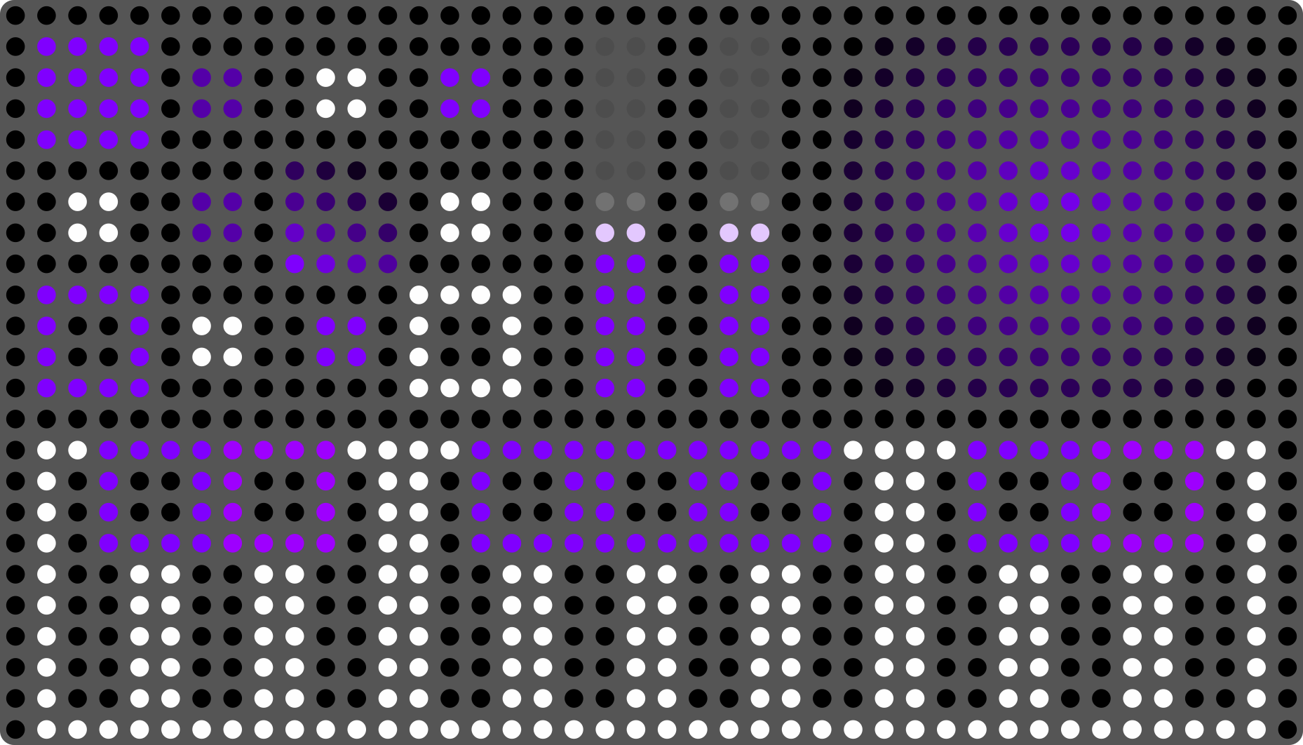
The Pad Grid
The playing surface is organised as a 42 × 24 LED grid -- 42 columns across and 24 rows top to bottom -- backed by a high-resolution Force-Sensitive Resistor (FSR) matrix. Each LED cell is supported by 16 raw sensing sites, giving more than 16,000 pressure-sensing locations across the playing area while keeping visual feedback aligned with the physical surface.
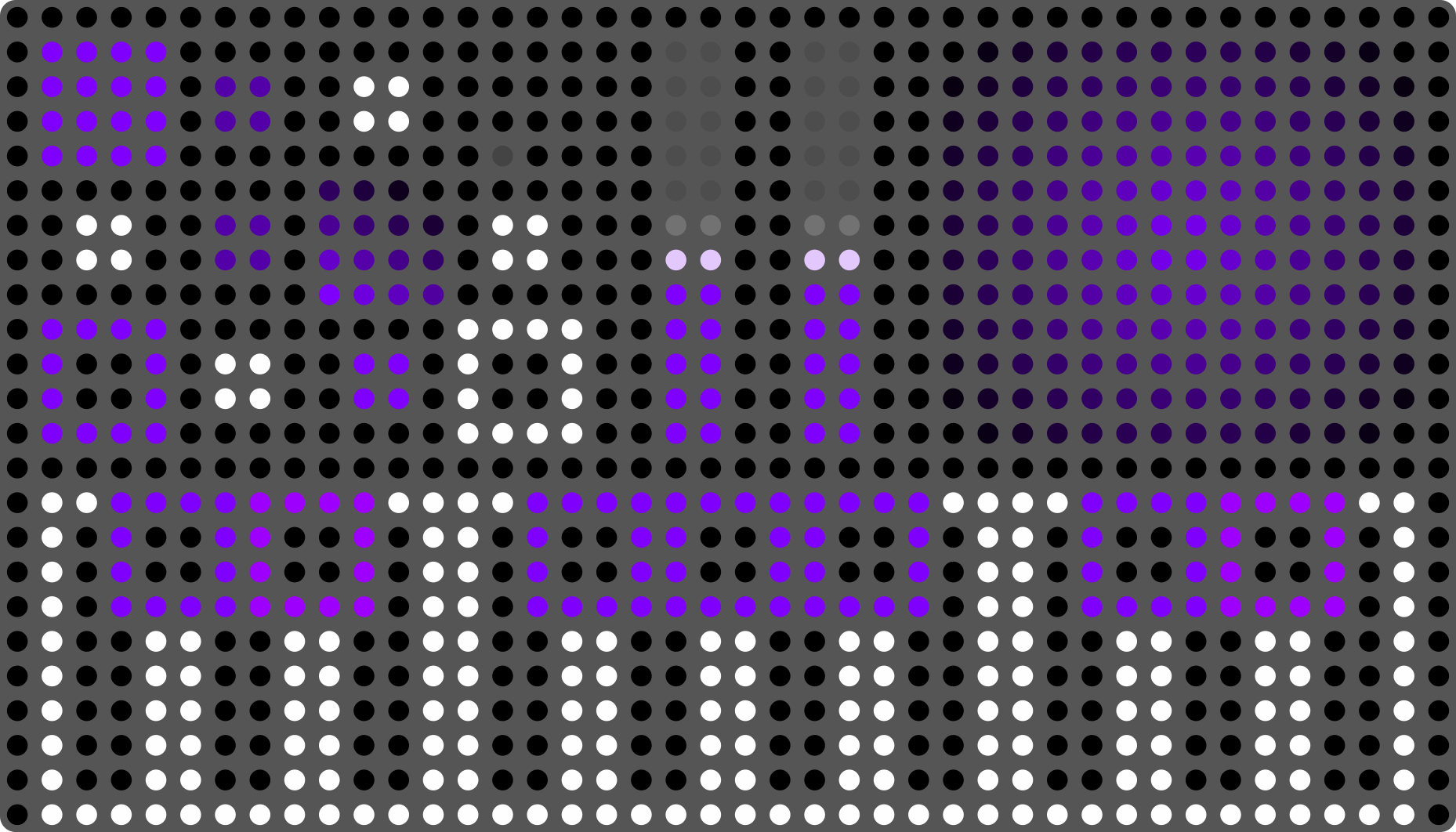
The physical grid is continuous: pad zones, faders, and keys can span any number of cells, so layouts are not constrained to a fixed button pitch. When a finger lands between cells the firmware interpolates position to sub-cell accuracy, giving smooth, high-resolution control.
Tip: Wider elements (spanning more cells) give you more room to slide and produce smoother X/Y data. Use narrow elements only when you need many zones in a small space.
XYZ Sensing
Each touch reports three independent dimensions simultaneously:
- X Position — horizontal position of the finger within its element, normalised
0.0–1.0(left to right). Sliding left or right generates X movement. - Y Position — vertical position within the element, normalised
0.0–1.0(top to bottom). Sliding up or down generates Y movement. - Z Pressure — force applied to the surface, normalised
0.0–1.0. Pressing harder increases Z.
The touch engine also derives Motion Speed from continuous finger movement across the surface. Motion Speed is smoothed at the detector level and normalized from 0 to 100 cm/s for MIDI CC and CV mappings.
Z is scaled so that a firm press reaches 1.0 well within the comfortable playing range.
Tip: Use X Position and Y Position on Key elements to drive pitch bend and modulation simultaneously — this is the core of expressive MPE playing. See Chapter 6 for MPE configuration.
The surface is scanned at 1,600 Hz. Erae 2 then applies Embodme's touch-processing layer to turn that raw scan stream into stable, expressive X/Y/Z finger data that feels playable rather than noisy or mechanical.
16-Finger Multitouch
Erae 2 tracks up to 16 simultaneous fingers across the entire surface. Each finger is independently identified and assigned a stable tracking ID for the duration of its contact, so dense chords and two-handed gestures receive independent continuous X, Y, and Z streams.
Finger detection uses an adaptive pressure threshold with online real-time calibration — there is no startup warm-up window to wait through. A finger is confirmed as active after 3 consecutive frames above threshold and is released after 8 consecutive frames below it, preventing spurious note-off events from brief pressure dips.
When two fingers come very close together (within approximately 1.5 cell widths) the firmware fuses their centroids to avoid phantom multi-touch artefacts, then separates them again as they diverge.
Tip: Lay both hands across the surface for cluster chords -- up to 16 fingers can be tracked independently as long as touches are not physically overlapping.
Velocity Curve Setting
The on-device Velocity Curve editor in Settings shapes how touch dynamics become MIDI note velocity. It is a global playing-response setting, not an element-by-element pressure curve.
- Threshold sets how much contact is required before velocity begins to rise.
- Drive changes how quickly the middle of the curve reaches higher velocities.
- Compand compresses or expands the response shape.
- Range limits the maximum velocity output.
The curve preview on the LCD updates while you adjust these values. Use it to match Erae 2 to your playing style: lighter settings for subtle finger playing, firmer settings when you want more resistance before high velocities.
Tip: If notes jump to maximum velocity too easily, raise Threshold or lower Drive. If notes feel too soft, lower Threshold or raise Drive.
Global Sensitivity
The Global Sensitivity setting (found in Settings -> Touch) controls how readily the surface registers a touch across the entire pad. Four modes are available:
| Mode | Description |
|---|---|
| XSensitive | Most responsive — reacts to the lightest contact. Best for players with a very light touch. May produce false triggers if the surface is touched accidentally. |
| Sensitive | Responsive — lower activation threshold than the default. |
| Safe | Default setting — balanced threshold suitable for most playing styles and environments. |
| XSafe | Least responsive — requires firmer contact to register. Reduces false triggers from clothing, cables, or light accidental contact. |
Tip: If you experience phantom notes or false triggers during performance, switch from
SafetoXSafe. If the surface feels unresponsive to light playing, trySensitiveorXSensitive. Global Sensitivity is the single most effective tuning adjustment for players new to FSR-based surfaces.
Physical Care
Erae 2 can be fitted with different playing skins. Treat the skin as part of the instrument, not as a replaceable drum head.
- Fabric skin: Designed for subtle finger performance and expressive surface control. Use clean hands where possible, avoid scraping or hard impacts, and clean stains carefully with isopropyl alcohol on a soft lint-free cloth. Do not soak the surface.
- Drum / black skin: Wipe with a slightly damp lint-free cloth, then dry it before storage. This skin can be played with sticks, but Erae 2 is still an electronic controller rather than an acoustic drum. Heavy drumming, sharp stick angles, or repeated high-force impacts can mark the skin and may shorten the product's life expectancy.
- All skins: Keep sharp objects, rings, picks, and abrasive materials away from the surface. Avoid excessive heat and prolonged direct sunlight. Store the instrument in a case when not in use.
- Before playing: Remove cables, tools, and other objects resting on the surface so the touch engine starts from a clean contact state.
Layouts
A layout is the fundamental building block of a project. It defines what the Erae 2 surface does: which elements are placed where, how they respond to touch, and what MIDI messages they send. Switching layouts lets you change the entire surface configuration in an instant — from a chromatic keyboard in one layout to a set of pressure-sensitive pads in the next.
What Is a Layout?
Each layout is an independent snapshot of the surface. It stores:
- Every element placed on the surface (keyboards, faders, buttons, and more)
- Each element's position, size, and shape
- All per-element MIDI parameters (channel, note range, CC assignments, MPE settings, etc.)
- The scale and tuning applied to keyboard elements
- The LED color scheme for that surface state
When you switch layouts, none of the element data from the previous layout carries over. Each layout is fully self-contained.
Tip: Think of layouts as "scenes" — you can dedicate one layout to melodic performance, another to rhythm pads, and a third to macro controls, then move between them without stopping your music.
Layouts per Project
Every project contains exactly 8 layouts, numbered 1 through 8. All 8 slots are always present; any slot that has not been configured yet is simply empty (the surface is blank and produces no output).
You do not need to fill all 8 slots. An empty layout slot is a valid, playable state — useful as a momentary mute or a performance pause.
Tip: Use an empty layout slot as a deliberate "silence" scene. Switching to it cuts all active touch events cleanly.
Switching Layouts on the Erae 2
Use the dedicated N1-N8 panel buttons to switch layouts. Pressing a numbered button loads the corresponding layout slot immediately. Empty slots are valid playable states and can be used as silence/mute scenes.
The LCD Home screen shows the active layout name, but there is no separate LCD layout selector or Next/Prev layout workflow on Erae 2.
LED Indicators
The left strip of LEDs on the surface doubles as a layout indicator. Each of the 8 positions in the strip corresponds to a layout slot. The active layout position glows at full brightness; other occupied slots glow dimly; empty slots are unlit.
This lets you see your current position in the layout sequence at a glance, even in a dark performance environment. The glow animation on the active slot pulses gently to distinguish it from a static dim indicator.
Tip: The LED indicators update the instant a layout switch completes — there is no visual lag between pressing the button and the strip updating.
Editing Layouts in Erae Lab
Layouts are created and edited in Erae Lab on your computer. From within Erae Lab you can:
- Drag elements onto the surface canvas and position them freely
- Configure every element's MIDI output, scale, and visual color
- Name each layout for easy identification in the LCD selector
- Copy, paste, and reorder layouts within a project
- Preview layout LED appearance before sending to the device
When Erae Lab is connected, layout edits autosave and flow to the device through the background sync/session link. You normally do not need to run a manual push/pull after every edit. Wait for transfer activity to finish before disconnecting USB.
Switching layouts while fingers are held releases touches from the old layout and reintroduces held fingers to the new layout. This prevents stuck notes and phantom touches during performance layout changes.
Elements
Elements are the building blocks of a layout. Each element occupies a rectangular region of the touch surface, defines what MIDI (or CV) data it generates, and determines how the LEDs beneath it are rendered. A layout can contain any combination of elements placed side by side or overlapping, giving you complete flexibility over how your performance surface is organized.
Every element has three shared properties:
- Geometry — position and size on the surface grid (x, y, width, height)
- Style — LED color, gradient, image, or behavior-driven visualization
- Animations — optional glow, ripple, or fade effects triggered by touch
Element-specific parameters — MIDI channel, CC numbers, note assignments, expressivity settings — are configured per element and do not affect other elements in the same layout.
See Chapter 4 for how to add, move, and resize elements within a layout, Chapter 14 for editing parameters using Erae Lab, and the Erae Lab User Manual, Chapter 7 for a full guide to configuring each element type in Erae Lab.
5.1 Iso Keyboard
The Iso Keyboard is an isomorphic grid instrument — the same interval relationship exists between any two adjacent pads, regardless of where you are on the surface. This means that any fingering or chord shape works identically in every key, making transposition trivial and scale patterns immediately transferable.
Notes are arranged in a rectangular grid of individually addressable pads (Key elements), each capable of full per-note MPE expressivity. Each pad tracks velocity, lift velocity, pressure (channel pressure or polyphonic), horizontal slide (X axis), vertical slide (Y axis), and vibrato independently.
Layout and tuning. The horizontal interval between adjacent pads is one semitone by default (semitonesLineOffset = 5), and the vertical interval between rows is configurable. The Scale setting filters which pads light up as scale tones versus chromatic passing notes, and whether off-scale pads are displayed at all (controlled by the Show Offscale toggle). The base note of pad (0,0) is set by Base Note, defaulting to C4.
Key Width / Key Height control how many surface grid cells each pad occupies. Setting these above 1 creates wider or taller pads with more pressure-sensitive area per note.
MPE. Enable MPE to allocate each simultaneous touch its own MIDI channel, allowing per-note pitch bend, pressure, and slide data to reach MPE-capable synthesizers without crosstalk. The MPE Master Channel can be set to channel 1 or 16 depending on the receiving instrument.
Arpeggiator. The Iso Keyboard has a built-in arpeggiator. See Chapter 8 for full details.
LED visualization. Scale-degree pads receive their color from the Scale Style array (one style per degree). Off-scale pads use the Off-Scale Style (which can be set to a dim color or disabled entirely). When a pad is touched, its intensity increases and an animation plays based on the element's Animation settings. The root note of the current scale is typically highlighted with a distinct color.
| Parameter | Description | Range | Default |
|---|---|---|---|
| Base Note | Pitch assigned to grid origin | C-1 -- G9 | C4 |
| Scale | Active musical scale | Chromatic, Major, Minor, … | Major |
| Key Width | Surface cells wide per pad | 1 -- 8 | 1 |
| Key Height | Surface cells tall per pad | 1 -- 8 | 1 |
| Semitones Line Offset | Vertical interval in semitones | 0 -- 63 | 5 |
| Degrees Line Offset | Vertical interval in scale degrees | 0 -- 63 | 3 |
| Show Offscale | Show off-scale pads | On / Off | On |
| Octave Fixed | Lock root octave across scale changes | On / Off | Off |
| MPE Enable | Enable MPE per-note channels | On / Off | Off |
| MPE Master Channel | MPE zone master channel | 1 / 16 | 1 |
| MIDI Channel | Base MIDI channel | 1 -- 16 | 1 |
| MIDI Group | Internal routing group | 0 -- 15 | 0 |
Tip: In isomorphic layout, the same chord shape — say, a major triad — works the same way no matter where you place your fingers. Use this to practice chord voicings in one position and then shift them freely.
Tip: Turn Show Offscale off and set Scale to Blues or Japanese to remove all off-scale pads. The result is a grid where every cell plays an in-scale note — perfect for improvisation without wrong notes.
5.2 Chroma Keyboard
The Chroma Keyboard renders a traditional piano-style layout on the touch surface: white keys occupy the full height of the element, and black keys appear as shorter pads overlaid in the upper portion. This layout is immediately recognizable to pianists and is useful when patch design or notation requires thinking in standard keyboard terms.
Unlike a physical piano, every key on the Chroma Keyboard has full pressure sensitivity. Horizontal position within a key is tracked as a slide dimension, enabling pitch-bend-like gestures on individual notes without leaving the key.
Key Width sets how many surface cells each white key occupies. Black keys are automatically sized to approximately 5/12 of the white key height. The number of visible keys scales with the element's width.
The Scale setting determines how keys are colored. In Chromatic mode, each of the 12 chromatic degrees receives its own color from the Chroma Styles array (giving black and white keys distinct colors). In a diatonic scale mode, scale-degree keys receive Scale Styles and off-scale keys receive the Off-Scale Style.
Glissando enables smooth pitch transitions as a finger slides horizontally between keys without lifting, using configurable interpolation. CC74 maps the vertical finger position within a key to MIDI CC 74 (brightness), following the MPE specification for timbre.
| Parameter | Description | Range | Default |
|---|---|---|---|
| Base Note | Lowest note at element left edge | C-1 -- G9 | C4 |
| Scale | Active scale for coloring | Chromatic, Major, Minor, … | Chromatic |
| Key Width | Surface cells per white key | 1 -- 8 | 2 |
| Glissando | Smooth slide between keys | Enabled / Disabled | Disabled |
| CC74 | Map vertical position to CC 74 | Enabled / Disabled | Disabled |
| MPE Enable | Enable MPE per-note channels | On / Off | Off |
| MIDI Channel | Base MIDI channel | 1 -- 16 | 1 |
Tip: Place a Chroma Keyboard element at the bottom of your layout spanning the full width for a performance keyboard, then add faders or buttons in the top portion for modulation controls — all within a single layout.
5.3 Drumpad
The Drumpad is a keyboard variant optimized for percussion. It uses the same isomorphic grid structure as the Iso Keyboard but defaults to a Chromatic scale, meaning each pad in the grid is mapped to consecutive MIDI notes without scale filtering. This makes it straightforward to assign pads to drum machine sounds where each note corresponds to a specific instrument.
Unlike melodic keyboards, the Drumpad layout prioritizes maximum pad density and individual note reachability. Each pad is typically configured with wider dimensions to provide a larger striking surface. Velocity sensitivity is particularly important here: the Drumpad inherits all key expressivity attributes including velocity curves, lift velocity, and pressure, so you can layer softer and harder hits naturally.
Arrangement. Pads are arranged left-to-right, bottom-to-top, with each row advancing by Key Width cells. The first pad (bottom-left) plays Base Note and each subsequent pad plays the next semitone. Standard General MIDI drum mapping begins at note C1 (MIDI note 24), though the base note is fully configurable.
LED visualization. Each pad receives its color from the Chroma Styles array keyed to its chromatic position (0–11), allowing you to color-code related sounds. For example, all kick-range pads could be red, snares green, and hi-hats blue.
| Parameter | Description | Range | Default |
|---|---|---|---|
| Base Note | Note assigned to first (bottom-left) pad | C-1 -- G9 | C4 |
| Key Width | Surface cells wide per pad | 1 -- 8 | 1 |
| Key Height | Surface cells tall per pad | 1 -- 8 | 1 |
| MIDI Channel | MIDI channel for all pads | 1 -- 16 | 1 |
| MIDI Group | Internal routing group | 0 -- 15 | 0 |
| Velocity Sensitivity | Velocity curve shape | curve index | Default |
Tip: For a classic 4×4 drum pad grid, set the element size to 8×8 cells and set Key Width and Key Height to
2. You get 16 pads each occupying a generous two-by-two cell footprint.
5.4 Fader 1D
The Fader 1D is a single-axis continuous controller that tracks vertical finger position within the element's bounds. As you slide your finger from bottom to top, it sends an absolute CC value from 0 to 127. The LED visualization fills from the configured center value toward the current value, showing the current value at all times even when not being touched.
Absolute position. The fader outputs an absolute Y position — meaning the value corresponds directly to where your finger is on the surface, not to how far it has moved. Lifting your finger and placing it at a new position immediately jumps the value to that position.
Pressure output. An optional secondary CC can be assigned to finger pressure (Pressure CC), allowing simultaneous value and pressure output from the same fader. This is useful for adding expression depth to a volume or filter fader.
CV output. A CV output can be assigned to the Y axis (Y Absolute CV) and to pressure (Pressure CV), making the Fader 1D usable in modular synthesizer contexts without a MIDI-to-CV converter. See Chapter 10 for CV output configuration.
Initial value. The Initial Y Value sets the fader's starting value when the layout is loaded. Default is 0x3F (center, 63).
Center value. The Center Y Value sets the visual zero point used by the LED fill. The fill is drawn between the center value and the current value, so a center of 0 looks like a traditional fader that fills from the bottom, while a center of 63 creates a bipolar center-detent fader that fills upward or downward from the middle. The center value defaults to 0 for newly created faders.
| Parameter | Description | Range | Default |
|---|---|---|---|
| CC Y Absolute | CC number for vertical position | 0 -- 127 | 7 (Volume) |
| Initial Y Value | Starting value on layout load | 0 -- 127 | 63 |
| Center Y Value | Visual zero point for the LED fill | 0 -- 127 | 0 |
| Pressure CC | Optional CC for finger pressure | 0 -- 127 / Disabled | Disabled |
| Y Absolute CV | CV output for vertical position | Output index / Disabled | Disabled |
| Pressure CV | CV output for pressure | Output index / Disabled | Disabled |
| MIDI Channel | MIDI channel | 1 -- 16 | 1 |
| MIDI Group | Internal routing group | 0 -- 15 | 0 |
Tip: Stack two Fader 1D elements side by side, each controlling a different CC, to create a pair of adjacent faders for stereo volume or send levels.
5.5 Fader 2D
The Fader 2D tracks both horizontal (X) and vertical (Y) finger position as independent absolute CC values, making it an XY pad controller. Touching the surface anywhere within the element immediately sets both axes to that position. The LED visualization uses a crosshair or dot style to indicate the current X/Y position, and can render from a configurable center point instead of always from the minimum corner.
Dual CC output. CC X Absolute and CC Y Absolute are assigned independently. A common assignment is CC 74 (brightness/timbre) on the X axis and CC 11 (expression) on the Y axis, or filter cutoff on X and resonance on Y.
Pressure. An optional Pressure CC adds a third dimension of control, useful for adding dynamics to pad-based sound design.
CV outputs. Both axes and pressure have corresponding CV outputs (X Absolute CV, Y Absolute CV, Pressure CV), allowing full three-axis CV control from a single element.
Initial position. Initial X Value and Initial Y Value set the starting coordinates when the layout is loaded (default 0x3F, center).
Center position. Center X Value and Center Y Value set the visual zero point used by the XY fill. The active area is drawn between the center point and the current X/Y position. With the default center of 0, 0, the pad behaves like the older from-corner rendering. Setting the center to 63, 63 creates a center-detent XY pad: moving right/up fills one quadrant, moving left/down fills the opposite quadrant, and a dim center crosshair remains visible as a reference when it is not covered by the active position.
| Parameter | Description | Range | Default |
|---|---|---|---|
| CC X Absolute | CC number for horizontal position | 0 -- 127 | 74 |
| CC Y Absolute | CC number for vertical position | 0 -- 127 | 11 |
| Initial X Value | Starting X on layout load | 0 -- 127 | 63 |
| Initial Y Value | Starting Y on layout load | 0 -- 127 | 63 |
| Center X Value | Visual zero point for X rendering | 0 -- 127 | 0 |
| Center Y Value | Visual zero point for Y rendering | 0 -- 127 | 0 |
| Pressure CC | Optional CC for finger pressure | 0 -- 127 / Disabled | Disabled |
| X Absolute CV | CV output for X axis | Output index / Disabled | Disabled |
| Y Absolute CV | CV output for Y axis | Output index / Disabled | Disabled |
| Pressure CV | CV output for pressure | Output index / Disabled | Disabled |
| MIDI Channel | MIDI channel | 1 -- 16 | 1 |
Tip: Use the Fader 2D as a performance XY controller for a software synthesizer's filter — X for cutoff and Y for resonance — while using the pressure dimension to modulate drive or saturation simultaneously.
5.6 Button
The Button element is a discrete trigger that sends a defined MIDI (or CV) message when touched, and a complementary message on release. It supports five distinct operating modes — Note, Control Change, Program Change, Control Voltage, and Tap Tempo — and a Latched option that toggles the button state between presses rather than acting as a momentary trigger.
Momentary vs. Latched. In momentary mode (default, latched = false), pressing sends the "on" message and releasing sends the "off" message. In latched mode, the first press sends the "on" message and the button holds its state; the next press sends the "off" message and releases it.
Note mode. Sends a Note On with configurable velocity on press and a Note Off on release. A CV Note output can be assigned alongside the MIDI note for simultaneous gate/pitch output in modular contexts.
CC mode. Sends CC Value A on press (or note on) and CC Value B on release (or in latched "off" state). Separate controller numbers can be assigned for A and B states, allowing a single button to engage and disengage two different CC values — useful for activating effects sends, toggling record arm states, or switching preset banks.
Program Change mode. Sends a program change (with optional bank select MSB/LSB) on press. In latched mode, a second program change (Program B with optional Bank B) is sent when the button is released back to its off state.
CV mode. Outputs a 0 V / 5 V gate signal to a configured CV output with no MIDI message. Use this to trigger modular envelopes, clocks, or logic gates directly from the touch surface.
Tap Tempo mode. Each press of the button taps the project BPM. The firmware measures the interval between successive taps and updates the project tempo accordingly. No MIDI channel or note assignment is required — the button acts purely as a tempo input source.
LED visualization. Buttons use dual-state styles: the Disabled Intensity (dim) state shows the button at rest, and the Enabled state (full brightness or a different color) shows the button active. Style options include Dual Intensity, Dual Color, Center Fill, and Image.
| Parameter | Description | Range | Default |
|---|---|---|---|
| Mode | Button message type | Note / CC / PC / CV / Tap Tempo | Note |
| Latched | Toggle vs. momentary | On / Off | Off |
| Note (Note mode) | MIDI note number | 0 -- 127 | 48 (C3) |
| Controller A (CC mode) | CC number for "on" state | 0 -- 127 | 0 |
| Value A (CC mode) | CC value for "on" state | 0 -- 127 | 127 |
| Controller B (CC mode) | CC number for "off" state | 0 -- 127 / Disabled | Disabled |
| Value B (CC mode) | CC value for "off" state | 0 -- 127 | 0 |
| Program A (PC mode) | Program number for "on" state | 0 -- 127 | 0 |
| Bank MSB A / LSB A (PC mode) | Bank select bytes for "on" state | 0 -- 127 / Disabled | Disabled |
| CV On/Off (CV mode) | CV output and voltage pair | Output index / Disabled | Disabled |
| MIDI Channel | MIDI channel | 1 -- 16 | 1 |
| MIDI Group | Internal routing group | 0 -- 15 | 0 |
Tip: Use a latched CC button with Controller A set to a filter bypass CC to create a touch-latching filter on/off toggle — press once to engage, press again to disengage, with the LED changing color to confirm state.
Tip: In Program Change mode with latching enabled, a single button can alternate between two presets: Program A selects preset 1 on first press, Program B selects preset 2 on the second press.
5.7 Key
The Key element is a single-note pad — essentially one key from an Iso or Chroma Keyboard, placed as a standalone element. It generates a Note On with velocity when touched and a Note Off when released, and supports the full suite of per-note expressivity: pressure, horizontal and vertical slide (as CC or relative CC), vibrato, and CV output.
Expressivity dimensions. Each dimension of touch is mapped independently:
- Velocity Tune — shapes the velocity curve from finger contact speed
- Lift Tune — shapes the lift velocity sent on Note Off
- Pressure Tune — shapes the aftertouch/pressure curve (can output channel pressure or polyphonic pressure)
- Vibrato Tune — detects horizontal micro-oscillation and maps it to pitch bend or a CC
- Pressure CC — optional parallel CC output for pressure (in addition to aftertouch)
- Motion Speed CC — CC output driven by continuous finger movement speed, independent of the velocity note value
- X Absolute CC / Y Absolute CC — absolute position on the X and Y axes as CC
- X Relative CC / Y Relative CC — relative motion on the X and Y axes as CC
- Key CV — CV pitch and gate outputs for modular use
Activate Same Keys. When enabled, touching any Key element tuned to the same note within the same MIDI group will share activation state — useful for building drum pad layouts where the same note appears in multiple locations.
The Key element is the building block used internally by all keyboard variants. Place it alone when you want a single large performance pad with full expressivity for one note — for example, a bass drone pad, a hi-hat trigger with pressure, or a macro modulation surface.
| Parameter | Description | Range | Default |
|---|---|---|---|
| Note | MIDI note to send | 0 -- 127 | 48 (C3) |
| Velocity Tune | Velocity curve | curve type + sensitivity | Default |
| Lift Tune | Lift velocity curve | curve type + sensitivity | Default |
| Pressure Tune | Pressure/aftertouch curve | curve type + sensitivity | Default |
| Vibrato Tune | Vibrato detection sensitivity | curve type + sensitivity | Default |
| Pressure CC | Additional CC for pressure | 0 -- 127 / Disabled | Disabled |
| Motion Speed CC | CC for continuous finger movement speed | 0 -- 127 / Disabled | Disabled |
| X Absolute CC | CC for horizontal position | 0 -- 127 / Disabled | Disabled |
| Y Absolute CC | CC for vertical position | 0 -- 127 / Disabled | Disabled |
| X Relative CC | CC for horizontal motion | 0 -- 127 / Disabled | Disabled |
| Y Relative CC | CC for vertical motion | 0 -- 127 / Disabled | Disabled |
| Key CV | CV pitch + gate output pair | Output index / Disabled | Disabled |
| MIDI Channel | MIDI channel | 1 -- 16 | 1 |
5.8 Ableton Launchpad
The Ableton Launchpad element transforms Erae 2 into a native Ableton Live session controller, communicating over the Ableton Launchpad protocol. LED colors, clip state, scene launch, and track control are driven by Ableton Live in real time through the bidirectional Launchpad MIDI protocol — Erae 2 appears to Live as a connected Launchpad device.
Position. The element can occupy the Full Width of the surface, the Left Half, or the Right Half. Full width uses the complete 42-cell horizontal span (or 41 cells with one column reserved). Splitting allows you to combine an Ableton session grid on one half with other elements — faders, keyboards, buttons — on the other.
Zoom Level. The Zoom Level setting scales the Launchpad grid representation between Small (default, showing more clips at once) and Large (enlarged cells for easier interaction at lower resolution).
The Ableton Launchpad element occupies the highest display priority, meaning it overrides LED rendering from other overlapping elements. Standard session clip launching, stop, record arm, solo, mute, and scene launch gestures follow the Launchpad protocol specification.
| Parameter | Description | Range | Default |
|---|---|---|---|
| Position | Element placement on surface | Full Width / Left Half / Right Half | Full Width |
| Zoom Level | Grid zoom | Small / Large | Small |
Tip: Combine the Ableton Launchpad element on the left half of the surface with a bank of Fader 1D elements on the right to have both session clip control and volume faders in a single layout without switching views.
5.9 API Zone
The API Zone element designates a region of the touch surface for direct programmatic control via the Erae 2 developer API. Rather than translating touches into MIDI, the API Zone passes raw finger tracking data — position (X, Y), pressure, and contact area — directly to a connected host application via a dedicated data stream.
This is intended for advanced integrations: custom Max/MSP patches, TouchDesigner setups, bespoke software instruments, or any application that wants full access to the raw multi-touch data without the MIDI abstraction layer.
Zone Index. Multiple API Zones can coexist in a layout, each identified by a unique Zone Index (0 -- 127). The host application reads the zone index to distinguish which region of the surface the data originates from.
Max Fingers. Max Num Fingers configures the maximum number of simultaneous touches reported per zone.
Data Rate. Finger Data Rate controls the frequency at which finger position updates are sent to the host.
The API Zone element has no LED visualization by default — the surface region appears unlit unless a style is explicitly assigned.
| Parameter | Description | Range | Default |
|---|---|---|---|
| Zone Index | Zone identifier for the host API | 0 -- 127 | 0 |
| Max Num Fingers | Maximum simultaneous touches reported | 1 -- 16 | 16 |
| Finger Data Rate | Update rate for finger position data | rate index | Default |
Developer API. The full SysEx wire protocol for finger streaming, LED drawing (
SetPixel,DrawRectangle,DrawImage), zone boundary queries, and version negotiation is documented in Appendix D: Developer API. Read the Y-axis section before correlating finger reports with drawing commands -- finger Y is bottom-origin, drawing Y is top-origin.
5.10 Pedal
The Pedal element is a non-visible element that configures one of the two pedal inputs (Pedal Input A or Pedal Input B) on Erae 2. It does not appear on the touch surface or produce any LED output — it exists solely to define how a connected pedal is interpreted and what MIDI or CV messages it generates.
The Pedal uses the PedalV2 data structure, which supports six distinct pedal types. Each type has its own parameter set tuned to the physical and musical role of that pedal.
Input assignment. Each Pedal element is assigned to a specific pedal input socket (Pedal Input A or Pedal Input B). Two Pedal elements can coexist in a layout, one for each input.
MIDI Output Destination. Like all MIDI-generating elements, the Pedal supports independent routing to USB Device, USB Host, TRS MIDI A, and TRS MIDI B outputs.
Switch
A standard momentary or toggle switch pedal. Sends a Note, CC, Program Change, or Tap Tempo message. In momentary mode, the message is sent on press and a complementary message on release; in latched mode, each press toggles between on and off states.
Message types:
- Note — sends Note On on press, Note Off on release
- CC — sends CC Value On to Controller On on press; CC Value Off to Controller Off on release (each independently enabled)
- Program Change — sends a Program Change (with optional bank select)
- Tap Tempo — taps the project tempo in sync with an external pedal press
A CV On/Off gate output can be assigned alongside any message type for simultaneous modular triggering.
| Parameter | Description | Range | Default |
|---|---|---|---|
| Latched | Toggle vs. momentary | On / Off | Off |
| Message Type | Note / CC / PC / Tap Tempo | — | Note |
| Note (Note mode) | MIDI note number | 0 -- 127 | 48 |
| Controller On (CC mode) | CC number for press | 0 -- 127 | 64 |
| Value On (CC mode) | CC value for press | 0 -- 127 | 0 |
| Controller Off (CC mode) | CC number for release | 0 -- 127 / Disabled | Disabled |
| Value Off (CC mode) | CC value for release | 0 -- 127 | 0 |
| CV On/Off | Gate CV output | Output index / Disabled | Disabled |
Kick
Optimized for kick drum pedals with impact detection. The Kick type detects the sudden downward force of a kick pedal strike, measures the velocity of the impact, and sends a Note On with velocity-mapped dynamic intensity. Note Off is sent either after a fixed duration or when the pedal returns above threshold.
| Parameter | Description | Range | Default |
|---|---|---|---|
| Note | Drum note to trigger | 0 -- 127 | 36 (C2) |
| Velocity Sensitivity | Impact velocity curve strength | 0 -- 100% | 100% |
| Impact Threshold | Minimum delta to trigger | 0.0 -- 1.0 | 0.1 |
| Duration Mode | Note Off timing | Fixed / Until Release | Until Release |
| Fixed Duration | Note duration in Fixed mode | ms | 100 ms |
| CV Gate | Gate CV output | Output index / Disabled | Disabled |
| CV Velocity | Velocity CV output | Output index / Disabled | Disabled |
Sustain (Binary)
A standard on/off sustain pedal. Sends CC 64 (Sustain) at a configurable on-value when pressed and an off-value when released. Designed for standard polarity sustain pedals. Polarity is fixed (press = low impedance = CC on); see the Expressive type if your pedal has inverted polarity.
| Parameter | Description | Range | Default |
|---|---|---|---|
| Controller | CC number | 0 -- 127 | 64 (Sustain) |
| On Value | CC value when pressed | 0 -- 127 | 127 |
| Off Value | CC value when released | 0 -- 127 | 0 |
| Latched | Toggle mode | On / Off | Off |
| CV On/Off | Gate CV output | Output index / Disabled | Disabled |
Expressive
A continuous expression pedal that maps pedal position to a CC value. The full pedal travel maps to the full CC range (0 -- 127). CC 11 (Expression) is the default assignment, following the standard for expression pedals. An Invert option reverses the mapping for pedals with reversed polarity.
A CV Pressure output is available for direct voltage output proportional to pedal position in modular contexts.
| Parameter | Description | Range | Default |
|---|---|---|---|
| Controller | CC number | 0 -- 127 | 11 (Expression) |
| Invert | Reverse pedal direction | On / Off | Off |
| CV Pressure | Continuous CV output | Output index / Disabled | Disabled |
Tip: Use an expression pedal in Expressive mode with CC 11 routed to a synth's volume for a natural swell control, while keeping your hands free on the touch surface for note playing.
Sustain Continuous
Functionally identical to the Expressive type but defaults to CC 64 (Sustain) and is intended for half-damper–capable sustain pedals that report continuous position rather than binary on/off. This allows progressive sustain depth when used with a compatible piano or keyboard sound engine.
| Parameter | Description | Range | Default |
|---|---|---|---|
| Controller | CC number | 0 -- 127 | 64 (Sustain) |
| Invert | Reverse pedal direction | On / Off | Off |
| CV Pressure | Continuous CV output | Output index / Disabled | Disabled |
HiHat
The HiHat type combines continuous pedal position output with intelligent chick detection. It continuously sends CC 4 (Foot Controller) proportional to pedal position, and detects the quick closure gesture of a hi-hat chick to trigger a Note On for the foot-chick sound.
Chick detection triggers when the pedal closes rapidly past the Closed Threshold (90% by default). The detection compares the rate of change of the pedal signal against the Chick Impact Threshold. A Chick Dead Time window prevents retriggering from slow pedal movements. The chick note duration is fixed at 50 ms by default.
CV outputs are available for both the gate signal (chick trigger) and the continuous pedal position.
| Parameter | Description | Range | Default |
|---|---|---|---|
| Controller | CC for continuous position | 0 -- 127 | 4 (Foot Controller) |
| Invert | Reverse pedal direction | On / Off | Off |
| Chick Note | MIDI note for foot chick | 0 -- 127 | 42 (F#1) |
| Chick Velocity Sensitivity | Chick velocity curve | 0 -- 100 | 50 |
| Chick Impact Threshold | Minimum delta to trigger chick | 0.0 -- 1.0 | 0.1 |
| Closed Threshold | Pedal position to enable chick | 0.0 -- 1.0 | 0.9 |
| Chick Duration | Note length for chick sound | ms | 50 ms |
| Chick Dead Time | Minimum time between chick triggers | ms | 100 ms |
| CV Gate | Gate CV output (chick trigger) | Output index / Disabled | Disabled |
| CV Continuous | Continuous CV output (position) | Output index / Disabled | Disabled |
Tip: For electronic drum kits, assign the HiHat pedal to Pedal Input B and a Kick pedal to Pedal Input A, then use the Drumpad element on the touch surface for snare, toms, and cymbals — giving you a complete three-limb electronic drum rig.
Tip: The Pedal element's routing (USB Device / USB Host / TRS MIDI A / TRS MIDI B) is configured independently from the touch surface elements. You can send kick drum notes over TRS MIDI A to a drum machine while sending everything else over USB Device to your DAW.
CV Clock Output — the project-level clock signal sent to a CV output — is covered separately in Chapter 10, as it is a project-wide setting rather than a per-element parameter.
MIDI Configuration
Erae 2 is a full-featured MIDI controller that generates standard MIDI 1.0 messages and supports MIDI 2.0 internally. Every element on the surface — keys, buttons, faders — carries its own MIDI channel, group, and output destination, giving you complete per-element control over where messages go and how they are expressed.
This chapter covers USB MIDI port layout, channel assignment, expressive parameter mapping, CC routing, MPE, high-resolution CC and NRPN, the physical MIDI routing matrix, and the built-in MIDI Monitor.
USB MIDI Ports
When Erae 2 is connected over USB in normal MIDI 1.0 mode, the host computer sees two user-facing MIDI cables inside a single USB MIDI device:
| Cable | Name | Purpose |
|---|---|---|
| Cable 0 | Erae 2 MIDI | Standard MIDI output — use this for most DAW and instrument routing |
| Cable 1 | Erae 2 MIDI (MPE) | MPE output — select this cable in your DAW for full expressive play; MPE messages always go to this cable |
Tip: When setting up an MPE instrument track in your DAW, point it at the
Erae 2 MIDI (MPE)cable. Standard non-MPE tracks should receive fromErae 2 MIDI.
MIDI 2.0 is an alternate USB mode controlled by Settings > MIDI 2.0: ON/OFF and requires rebooting the device. Do not route a MIDI 2.0 cable manually in your DAW unless a specific workflow tells you to do so.
MIDI Channel and Group
Every element that generates MIDI output has two addressing fields:
| Parameter | Range | Default | Description |
|---|---|---|---|
| MIDI Channel | 1–16 (stored as 0–15) | 1 | MIDI channel for this element's output |
| MIDI Group | 1–16 (stored as 0–15) | 1 | MIDI 2.0 UMP group number |
MIDI Channel determines which of the 16 standard MIDI channels carries the element's Note On/Off, CC, and Program Change messages. Each element on the surface can use a different channel, so a single layout can simultaneously drive multiple instruments or parts in your DAW.
MIDI Group is the MIDI 2.0 Universal MIDI Packet group number. In standard MIDI 1.0 mode the group field is not transmitted on the wire. It is orthogonal to MPE zone selection — see the MPE section below for how zones are configured.
Tip: Assign adjacent keys the same MIDI channel when you want chords to share a single channel-pressure stream, or assign each key its own channel for full per-note independence in MPE mode.
Per-Element Output Destination
Each element also carries a MIDI Output Destination bitmask that selects which physical ports transmit its messages. You can enable any combination of the four available ports simultaneously:
| Flag | Port |
|---|---|
| USB Device | USB Device (device-to-host, your computer) |
| USB Host | USB Host (host-to-device, external USB gear) |
| MIDI A | MIDI output jack A |
| MIDI B | MIDI output jack B |
The default for all element types is USB Device only. Enabling additional destinations does not change the channel or group — the same message is replicated to every selected port.
Tip: Use MIDI B as a dedicated clock/transport output and keep MIDI A for note data, so analog gear receives tight sync without channel conflicts.
Key Element — Expressive Parameters
Key elements are the primary expressive touch zones. A key generates Note On at contact, tracks pressure and position while held, and sends Note Off on release. The following parameters tune exactly how touch data maps to MIDI messages:
Velocity
| Parameter | Range | Default | Description |
|---|---|---|---|
| Velocity Intensity | 0–127 | 63 | Scales attack velocity derived from initial contact speed |
Velocity is computed from the rate of pressure increase at note-on. Higher intensity values produce wider velocity swings for a given touch speed.
Lift Velocity
| Parameter | Range | Default | Description |
|---|---|---|---|
| Lift Intensity | 0–127 | 63 | Scales the Note Off velocity from release speed |
Lift velocity is sent in the Note Off message. Set to 0 to always send a fixed Note Off velocity of 0.
Pressure
Pressure is the continuous force applied after note-on. Erae 2 can send pressure as either Poly Aftertouch (per-note) or Channel Pressure (mono):
| Parameter | Range | Default | Description |
|---|---|---|---|
| Pressure Type | PolyPressure / ChannelPressure | ChannelPressure | Message type used for pressure output |
| Tracking | LastPlayed / Highest / Lowest / None | None | For Channel Pressure: which finger drives the value when multiple fingers are held |
| Min Value | 0–127 | 0 | Pressure output lower bound |
| Max Value | 0–127 | 127 | Pressure output upper bound |
| Intensity | 0–255 | 127 | Sensitivity curve steepness |
| Smoothing | 0–255 | 0 | Low-pass smoothing applied to pressure readings |
| Filter | Exponential / others | Exponential | Interpolation filter shape |
Tip: For MIDI 1.0 MPE instruments, member-channel ChannelPressure is usually the safest default because each finger already has its own member channel. In MIDI 2.0 paths, per-note PolyPressure can carry note-specific pressure directly. For traditional non-MPE synthesizers with a single aftertouch input, use
ChannelPressurewithTracking: Highest.
Warning: In non-MPE mode, multiple simultaneously-held keys share a single MIDI channel. If
PolyPressureis selected, each note's pressure message is tagged with its note number, but many instruments map all poly pressure to a single value anyway. IfChannelPressureis selected, only one pressure value is sent per channel — multiple fingers contend for that single stream. Enable MPE for true per-note pressure independence.
Vibrato (Pitch Bend / Glissando)
The Vibrato block controls how horizontal finger movement maps to pitch bend. The pitch bend range must match the setting in your synthesizer for accurate semitone tracking.
| Parameter | Range | Default | Description |
|---|---|---|---|
| Pitch Bend Range | 1–96 semitones | 12 (standard), 48 (MPE) | Semitone range of the pitch bend message |
| Style | Linear / others | Linear | Mapping curve from position to pitch bend value |
| Intensity | 0–127 | 127 | Maximum pitch bend deviation |
| Smoothing | 0–127 | 127 | Temporal smoothing of pitch bend output |
The Glissando block controls pitch quantisation while sliding between notes:
| Parameter | Range | Default | Description |
|---|---|---|---|
| Tune Location | Pad / Finger | Pad | Reference point for zero pitch bend — centre of key or initial finger position |
| In-Tune Width | 0–100 % | 50 % | Width of the chromatic "snap" zone as a percentage of key width |
| Retrigger | on / off | off | Re-sends Note On when crossing to a new key pitch while sliding |
| Smoothing | 0–255 | 63 | Smoothing for glissando position output |
| Y Disabled | on / off | off | Disables vertical axis contribution to pitch |
Tip: Set In-Tune Width to
100 %to completely suppress pitch bend within a key — useful for chromatic pads where you want clean semitones without any microtonal drift.
CC Mapping
Key elements and fader elements can generate Continuous Controller messages from touch position and pressure. The available CC axes are:
| CC Slot | Axis | Element Types |
|---|---|---|
| CC Pressure | Contact force (Z) | Key, Fader 1D, Fader 2D |
| CC X Absolute | Horizontal position within element | Key, Fader 2D |
| CC Y Absolute | Vertical position within element | Key, Fader 1D, Fader 2D |
| CC X Relative | Horizontal delta from centre | Key |
| CC Y Relative | Vertical delta from centre | Key |
| CC Motion Speed | Continuous finger movement speed | Key, Fader 1D, Fader 2D |
Each CC slot has an enable flag and a controller number (0–127). Disabled slots send no data. Absolute CC axes track the finger's position across the full physical extent of the element. Relative CC axes output a value centred around the configurable initial value (default approximately 64) at rest and deviate based on displacement from centre. Motion Speed CC follows detector-level movement speed, smoothed and normalized from 0 to 100 cm/s.
Button CC elements send two fixed CC values: value A on press, and — when Latched — value B on a second press. Each value has an independent controller number and can be independently disabled.
Tip: Map CC Y Absolute on a tall key to filter cutoff to create a ribbon-style expression strip within a single pad.
High-Resolution CC and NRPN
Erae 2 handles MIDI 2.0 Control Change messages internally with 32-bit resolution. When outputting over MIDI 1.0 ports, standard 7-bit CC is used by default. For applications requiring higher resolution over MIDI 1.0, the following options are fully implemented:
- 14-bit CC (High-Resolution CC): Paired MSB + LSB messages following the MIDI specification. The MSB is sent on the primary CC number (index 0–31) and the LSB on CC number +32. The firmware transmits both messages automatically — no host configuration is required.
- RPN (Registered Parameter Number): Fully implemented. Used internally for MPE pitch bend range advertisement and available for other standard RPN uses.
- NRPN (Non-Registered Parameter Number): Fully implemented. NRPN addresses can be targeted through the Button Program Change element type, which supports Bank MSB, Bank LSB, and Program Number in a single press event — covering standard NRPN address and value transmission patterns.
Tip: To send a 14-bit CC value, configure your element's CC number in the range 0–31. The firmware automatically sends the paired LSB on CC number +32 for full 14-bit resolution.
MPE Configuration
MPE (MIDI Polyphonic Expression) allows each finger to have independent pitch bend, pressure, and slide on its own MIDI channel, enabling per-note expression across polyphonic patches.
Erae 2 implements two MPE zones defined by the MIDI MPE specification. The zone is set per keyboard element via the Master Channel setting:
| Master Channel Setting | MPE Zone | Member Channels |
|---|---|---|
| Ch 1 (default) | Lower Zone | Ch 2 up to Ch N (allocated dynamically) |
| Ch 16 | Upper Zone | Ch 15 down to Ch (16−N) (allocated dynamically) |
The MIDI Group parameter is the MIDI 2.0 UMP group number and is orthogonal to MPE zone selection. MPE zone is determined by the Master Channel setting on the keyboard element. When MPE is enabled, the channel selector becomes the master-channel selector, and the stored keyboard channel value is used internally as the member-channel count.
MPE messages are always output on the Erae 2 MIDI (MPE) USB cable (cable 1). See the USB MIDI Ports section at the top of this chapter.
MPE-relevant settings per keyboard element:
| Setting | Recommended MPE Value |
|---|---|
| MPE Enable | on |
| MPE Master Channel | Ch 1 (Lower Zone) or Ch 16 (Upper Zone) |
| Pitch Bend Range | 48 semitones |
| Pressure Type | ChannelPressure for MIDI 1.0 MPE; PolyPressure where MIDI 2.0 per-note pressure is used |
| CC Y Absolute | CC 74 (Slide / Timbre) |
Tip: Most MPE synthesizers expect pitch bend range to be set identically on both the controller and the instrument. Set Pitch Bend Range to
48in the element editor and use the instrument's own MPE setup page to match.
MIDI Routing Matrix
The routing matrix controls which physical ports relay MIDI input messages to other ports, independently of element output destinations. This allows Erae 2 to act as a MIDI merge and thru box.
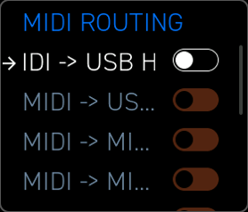
The routing screen is accessed from the LCD menu under Settings > MIDI Routing. Each row is a toggle switch:
| Switch | Source -> Destination | Effect |
|---|---|---|
| MIDI In -> USB Host | MIDI In -> USB Host Out | Forward hardware MIDI In to connected USB devices |
| MIDI In -> USB Device | MIDI In -> USB Device Out | Forward hardware MIDI In to the host computer |
| MIDI In -> MIDI Out A | MIDI In -> MIDI A Out | MIDI Thru to MIDI A |
| MIDI In -> MIDI Out B | MIDI In -> MIDI B Out | MIDI Thru to MIDI B |
| USB Device -> USB Host | USB Device In -> USB Host Out | Route host computer MIDI to connected USB device |
| USB Device -> MIDI Out A | USB Device In -> MIDI A Out | Route host computer MIDI to hardware gear on MIDI A |
| USB Device -> MIDI Out B | USB Device In -> MIDI B Out | Route host computer MIDI to hardware gear on MIDI B |
| USB Host -> USB Device | USB Host In -> USB Device Out | Route connected USB device MIDI to host computer |
| USB Host -> MIDI Out A | USB Host In -> MIDI A Out | Route connected USB device to hardware gear on MIDI A |
| USB Host -> MIDI Out B | USB Host In -> MIDI B Out | Route connected USB device to hardware gear on MIDI B |
Turn a switch on to enable that routing path. All routing switches are independent — multiple sources can feed the same destination.
Tip: To use Erae 2 as a simple 2-port MIDI interface, enable MIDI In -> USB Device and USB Device -> MIDI Out A. Your DAW can then send to and receive from hardware synths through Erae 2 without any additional interface.
Routing settings are saved per Project, so each layout preset can carry its own merge configuration.
MIDI Monitor
The MIDI Monitor displays a live scrolling log of all outgoing MIDI messages generated by the surface. It is useful for verifying that elements are sending on the correct channels and that expressive data (pressure, pitch bend, CC) is moving as expected.
Access the monitor from the LCD menu under Settings > MIDI Monitor. The screen shows up to 30 lines of recent messages. Each line contains:
| Column | Description |
|---|---|
| Time | Relative timestamp in tenths of a second since the previous message |
| Ch | MIDI channel (and group for MIDI 2.0 messages) |
| Type | Message type abbreviation |
| Value | Message payload — note name + velocity, CC index + value, etc. |
Message types displayed:
| Abbreviation | MIDI Message |
|---|---|
N ON | Note On (note name, velocity shown as 16-bit MIDI 2.0 value) |
N OFF | Note Off (note name, release velocity) |
PP | Poly Pressure (note name, 32-bit pressure value) |
CC | Control Change (controller index, 32-bit value) |
PC | Program Change (program number) |
AT | Channel Pressure / Aftertouch (32-bit value) |
PB | Pitch Bend (32-bit value) |
Note names are displayed using standard chromatic notation: C, C#, D, D#, E, F, F#, G, G#, A, A#, B, with octave number appended.
The monitor captures MIDI 2.0 resolution values internally and displays them as 16-bit (velocity) or 32-bit (pressure, pitch bend, CC) integers. When messages are converted to MIDI 1.0 for output on physical ports, they are scaled down to 7-bit or 14-bit resolution automatically.
Tip: If a key is not sounding in your instrument, open the MIDI Monitor and touch the pad — if no
N ONline appears, the element may be disabled or assigned to a destination port that is not connected. If a line appears but the instrument does not respond, check that the MIDI channel shown matches the instrument's receive channel.
Related Topics
- Elements — per-element type configuration details including button CC and program change setup
- LCD Interface — navigating menus on the LCD display
- Settings — project-level settings including MIDI clock and sync
- MIDI Implementation — complete message reference table
Scales & Tuning
Scale settings are per keyboard element, not global. Each keyboard element in a layout stores its own scale, root note, and octave independently. The Scale screen edits the settings for the currently selected element — switch to a different element before opening the Scale screen to configure it separately.
The Scale screen controls how the selected keyboard element interprets touch coordinates as musical pitches.
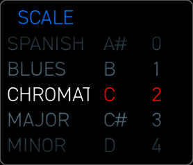
Press the Scale button on the front panel to open the Scale screen. The display is divided into three columns: Scale, Root Note, and Octave. Use the encoder or touch the column to scroll each roller independently.
Built-In Scale Library
The Scale roller lists the factory scale library. Factory scales are fixed and cannot be edited or deleted on the device.
The built-in library contains exactly 15 factory scales covering common Western and non-Western scale types:
Chromatic— all 12 semitones; disables scale filteringMajor— the standard diatonic major scaleMinor— natural minor (Aeolian mode)Melodic Minor— raised sixth and seventh ascendingHarmonic Minor— raised seventh degreeArabicDorianPhrygianGypsyMixolydianRomanianGypsy MinorJapaneseSpanishBlues
Tip: Selecting
Chromaticis equivalent to "no scale filter" — every semitone is available and the surface behaves like a full keyboard with no hidden notes.
Root Note
The Root Note roller sets the tonal center of the selected scale. Twelve values are available: C, C#, D, D#, E, F, F#, G, G#, A, A#, B.
The root note determines which pitch class is treated as degree 0 (the tonic). Changing the root transposes the entire scale without altering its interval structure.
Tip: On an Isomorphic keyboard with Show Offscale enabled, keys that fall on the root note are highlighted with the tonic style color, making the tonal center immediately visible on the surface.
Octave Offset
The Octave roller shifts the base octave of the keyboard element up or down in whole-octave steps. The default value of 0 maps the base note to the octave configured in the element itself. Positive values raise the register; negative values lower it.
The Octave roller offers the range -2 to +8, giving a practical span of ten octaves above and below the element's base note. The available range is wide enough to accommodate most synthesizer pitch requirements without needing to edit the element's base note directly.
Tip: Use the octave offset to quickly bring a keyboard into the range expected by your synthesizer without editing the underlying element note assignment.
Show Offscale
The Show Offscale toggle (the icon button below the Scale roller) controls whether off-scale semitones appear on the surface. This label matches the UI button on the LCD.
- On — all 12 semitones are visible. Notes in the scale receive the scale-degree color style; notes outside the scale receive the off-scale style. You can still touch any semitone.
- Off — only scale degrees are shown. The surface re-maps so that every physical cell plays a note that belongs to the selected scale; no off-scale semitones are accessible.
Tip: Turning Show Offscale off makes it impossible to play a "wrong" note, which is ideal for live performance, improvisation, and beginners. The surface becomes a constrained instrument that stays in key.
How Scales Affect Each Keyboard Type
| Keyboard Type | Scale support | Show Offscale toggle? |
|---|---|---|
| Iso Keyboard | Full — filters and highlights scale degrees, controls step intervals | Yes |
| Chroma Keyboard | Coloring only — no scale filtering, notes follow chromatic layout | No |
| Drumpad | None — always chromatic; scale panel is hidden | No |
Iso Keyboard has the richest scale interaction: the scale also controls the horizontal and vertical step intervals. When Show Offscale is off, each row step equals one scale degree rather than one semitone, so the isomorphic geometry is preserved within the scale.
Chroma Keyboard uses the scale only for visual coloring of keys. The chromatic layout is fixed — all 12 semitones are always accessible regardless of scale selection.
Drumpad ignores scale settings entirely; the scale panel is not shown in Erae Lab when a Drumpad element is selected. Each pad maps sequentially to consecutive MIDI notes starting from the base note.
Per-Element Scale Settings
Each keyboard element stores its own scale assignment independently. The Scale screen always edits the scale of the currently selected element — the element whose mapping view is active on the LCD. To configure different scales on different elements, select each element in turn via the Mapping button and return to the Scale screen to apply the desired settings.
Tip: You can create a layout where one element plays Japanese scale while another plays Blues or Major — useful for layered instruments or split-surface setups.
Arpeggiator & Looper
Erae 2 provides two real-time performance tools: the Arpeggiator, which generates melodic patterns from held notes, and the Looper, which records and replays your playing as a repeating pattern synchronized to the project clock.
Arpeggiator
The Arpeggiator turns held notes into a rhythmic sequence. It is assigned per keyboard element and can run on any Chromatic, Isomorphic, or Drumpad keyboard in your layout.
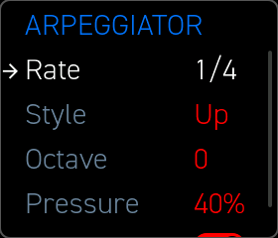
To open the Arpeggiator settings, press the Arp button on the front panel while a keyboard element is selected.
Enabling the Arpeggiator
At the top of the Arpeggiator screen is a mute/enable control. When the arpeggiator is disabled, notes play normally. When enabled, held notes are sustained silently and the arpeggiator emits timed note events instead.
Rate
Rate sets the rhythmic subdivision at which arpeggiated notes are triggered. Available values:
1/32, 1/16, 1/8, 1/4, 1/2, 1/1, Pressure
In Pressure mode, the arpeggiator fires a new note step each time finger pressure crosses the trigger threshold rather than firing on a time-based grid — useful for expressive, pressure-driven rhythms.
Rate is synchronized to the project tempo when Quantize is enabled (see below). When Quantize is off, Rate acts as a free-running interval in milliseconds.
Tip:
1/16is the most common starting point for fast melodic arpeggios. UsePressuremode for a completely expressive, free-rhythm arpeggio driven by how hard you press rather than the clock.
Style
Style determines the order in which held notes are played:
Up— notes are played from lowest to highest pitch, then repeatDown— notes are played from highest to lowest pitch, then repeatUpDown— notes ascend then descend before repeating; the turning note at the top and bottom is not duplicatedUpAndDown— notes ascend then descend before repeating; the turning note at the top and bottom is played twice (once on the way up, once on the way down)Random— each step picks a random note from the held set
Tip:
UpDownover a four-note chord produces a seven-step pattern (4 up + 3 down without repeat at the turning notes), which creates interesting polyrhythmic phasing when the rate does not divide evenly into the bar. UseUpAndDownwhen you want the turning notes accented by their doubled appearance.
Octave Range
Octave sets how many octaves the arpeggiator spans above (or below) the played notes. Range: 0 -- 8.
At 0, no octave expansion is applied — the arpeggio stays entirely within the register of the held notes. At 1, the arpeggiator plays the held notes once, then repeats them an octave higher. At 8, eight octave passes are completed before the cycle restarts.
The direction of octave traversal follows the selected Style: an Up style climbs through the octave range before cycling back.
Tip: A
Downstyle with Octave3and Rate1/16produces a cascading descending arpeggio that spans three octaves — a dramatic effect on pads and plucked instruments. Set Octave to0when you want tight, single-register arpeggiation without any octave jumping.
Pressure to Velocity
Pressure maps the touch pressure of held notes to the velocity of arpeggio note-on events. Range: 0% -- 100%. The parameter value is entered as a percentage (not a raw MIDI value).
At 0%, arpeggiated notes are emitted at a fixed velocity (the velocity captured at the moment of the initial press). At 100%, the velocity of each arpeggio step is modulated in real time by how hard you are currently pressing each held finger. Values between 0% and 100% blend between fixed and live-modulated velocity.
Tip: Set Pressure to
60%--80%for expressive playing where subtle changes in finger weight create natural velocity accents, while maintaining a stable overall dynamic.
Quantize
The Quantize toggle links the arpeggiator's rate to the project clock. This label matches the LCD display.
- On — Rate values are musical subdivisions, locked to the project tempo. The arpeggiator restarts at bar boundaries when you engage notes.
- Off — Rate is a free interval in milliseconds, independent of tempo.
Tip: Disable Quantize when performing without a metronome or external clock for a free, tempo-agnostic arpeggio. Re-enable Quantize when recording into a DAW to keep everything grid-aligned.
Looper
The Looper records, plays back, and overdubs MIDI performance data in a repeating pattern. It captures free, expressive playing in real time -- including pressure, slide, and continuous expression data.
Each layout can have one active Looper instance, shown on the Home screen.
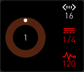
Home Screen Looper Display
When a Looper is active, the Home screen shows the following information:
- Loop circle — a circular display showing the layout number of the currently active loop. This is the current behavior: the circle identifies which layout's loop is active, not a playback position indicator.
- Length — the pattern length in steps.
- Tempo — the current BPM of the project clock.
- Quantize Grid — the quantization grid applied to recorded events (e.g.,
1/16).
Record and Playback
The Play/Rec button on the front panel controls the looper transport:
- First press — starts recording. The looper captures all MIDI output from keyboard elements in the current layout for one loop length, then automatically switches to playback.
- Stop — stops playback. The recorded pattern is retained in memory and resumes from the start when Play is pressed again.
Overdub is always active. The looper continuously overdubs new performance material onto the existing recording during playback — there is no separate overdub mode to enter. Every touch on keyboard elements is layered onto the loop as long as it is playing.
Deleting a recorded layer. To clear the last recorded layer for the current page, hold the Page button and press Return/Undo.
Tip: Because overdub is always on, shorter loop lengths tend to fill up quickly. Use the Length control to set an appropriate loop size before starting to record.
Looper Controls
There is no separate Looper Settings screen. All looper controls are available directly on the Home screen:
Quantize — the quantization grid applied to recorded note-on and note-off events. Values: Off, 1/4, 1/8, 1/16, 1/32. Quantization is applied non-destructively at playback time.
Tempo — the current project BPM. Adjust this to set the clock rate for the looper.
Length — the pattern length in steps. Select with the encoder and turn to adjust.
Tip: Record with quantization
Offto preserve natural expressive timing, then dial in1/16quantization to tighten up rhythmic feel without re-recording.
Note: Swing is not available in the current firmware version.
Clock Sync
The Looper is always locked to the project clock. When the project clock source is Internal, the Looper derives its tempo from the project BPM. When the clock source is USB-dev, MIDI, or USB-host, the Looper follows the incoming MIDI clock, allowing tight synchronization with a DAW or hardware clock source.
See Chapter 15 — Settings for clock source configuration.
Pattern Length
Pattern length is set using the Length control on the Home screen (in steps). Adjust it with the encoder before or after recording to define the loop window.
Quantize Grid
The Quantize Grid determines the rhythmic resolution at which recorded note-on and note-off events are snapped. Values: Off, 1/4, 1/8, 1/16, 1/32.
Quantization is applied non-destructively at playback time — the raw capture is retained so you can change the grid without re-recording.
Tip: Expression data (pressure, slide) is never quantized — only note-on and note-off timestamps are affected by the quantize grid. Your dynamics and vibrato remain smooth regardless of grid setting.
Tap Tempo
Tap Tempo allows you to set the project BPM by tapping in time rather than dialing a number. To use Tap Tempo:
- Configure a Pedal Input element (Switch type) with the Tap Tempo message type. Each press of the connected pedal taps the tempo.
- Alternatively, use a Button element on the touch surface set to Tap Tempo mode (see §5.8).
The firmware averages the interval between successive taps and updates the project BPM in real time. The Looper and Arpeggiator immediately follow the new tempo.
CV Outputs
Erae 2 provides 24 CV output channels via its rear panel. These outputs can carry pitch voltages, gate signals, or assignable control voltages, making Erae 2 a full-featured modular interface alongside its MIDI capabilities.
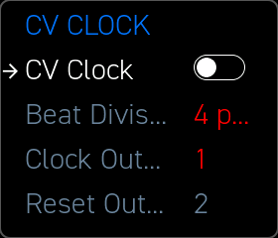
Hardware Overview
The Erae 2 rear panel exposes 24 CV outputs on 3.5 mm jacks. Each output is independently configurable in software. The hardware specifications are:
- Output range:
−5 V--+8 V(bipolar) - Pitch standard: 1 V/octave
- Resolution: 12-bit DAC per output
- Output impedance: low (suitable for direct connection to Eurorack and other synthesizer CV inputs)
All 24 outputs are available simultaneously with no multiplexing — each carries an independent, continuously updated voltage.
Output Modes
Each CV output is assigned a mode from within the element or project settings. Three fundamental modes are available:
Pitch (1V/oct) — the output carries a pitch voltage following the 1 V/octave standard. Middle C (MIDI note 60) outputs 2 V. The formula is: voltage = note / 12 + (−3.0 V). Each semitone is 1/12 V (≈ 83.3 mV). The hardware output range of −5 V to +8 V covers approximately 11 octaves.
Gate — the output is 0 V when no note is held and jumps to 5 V when a note is active. Gate is fixed at 5 V. Gate duration follows the note-on / note-off timing from the touch surface.
Control (0–5 V) — the output carries a continuous control voltage proportional to a parameter value, such as fader position, finger pressure, or slide position. By default the full 0% -- 100% parameter range maps to 0 V -- 5 V. The minimum and maximum voltages are configurable up to the hardware limits.
Tip: Use a Pitch output paired with a Gate output on adjacent channels for a classic V/oct + Gate pair to drive a monophonic analog synthesizer. Assign both outputs to the same keyboard element's first voice.
Per-Element CV Assignment
CV outputs are assigned within the element configuration (accessible via the Mapping screen). Each keyboard element can drive multiple CV voices. The CV Num Voice parameter in the keyboard element specifies how many simultaneous CV voices (polyphony) the element drives. Each voice occupies one pitch output and one gate output.
For example, setting CV Num Voice to 4 on an Isomorphic keyboard reserves four pitch outputs and four gate outputs starting from the assigned base output channel. Voicing follows a round-robin allocation across the available outputs.
Tip: For a four-voice paraphonic patch, assign CV Num Voice to
4and connect the four pitch outputs to a keyboard-tracking poly VCO. Connect the four gate outputs to a quad envelope generator for independent per-note envelopes.
Additional CV Outputs per Voice
Beyond the core Pitch and Gate pair, each voice can output additional expression streams as CV signals. Each stream consumes one additional CV channel per voice. The following per-voice CV outputs are available:
| Output | Description |
|---|---|
| Velocity | Initial strike velocity of the note (0–5 V) |
| Pressure | Continuous finger pressure (aftertouch), normalized to 0–5 V |
| X Position | Absolute horizontal finger position within the element, 0–5 V |
| Y Position | Absolute vertical finger position within the element, 0–5 V |
| X Slide | Relative horizontal movement (delta from note-on X), centered at 2.5 V |
| Y Slide | Relative vertical movement (delta from note-on Y), centered at 2.5 V |
| Motion Speed | Continuous finger movement speed, smoothed and normalized from 0 to 100 cm/s, 0–5 V |
Enable these outputs per-element in the Mapping screen. Assigning 4 voices with all seven optional outputs reserves 4 × (2 + 7) = 36 channels — plan channel allocation carefully across all elements.
Tip: Use Pressure CV to drive a VCA for note-level dynamics entirely in the modular domain. Pair with X Slide to control vibrato depth via an LFO depth CV input.
Eurorack Quickstart
First Voice Setup (Pitch + Gate)
- In Erae Lab, create an Isomorphic Keyboard element and set CV Num Voice to
1. - Assign the base output channel (e.g., channel 1). This reserves channel 1 for Pitch and channel 2 for Gate.
- Connect channel 1 (3.5 mm jack) to your Eurorack VCO's V/oct input.
- Connect channel 2 to your Eurorack envelope generator's Gate input.
- Play a note — the VCO tracks pitch at 1 V/octave, and the envelope fires on each note-on.
USB Host MIDI to Eurorack
Connect a USB-MIDI-to-CV module (e.g., Expert Sleepers FH-2 or Intellijel uMIDI) to the Erae 2 USB Host port. Configure the external module to receive MIDI from Erae 2 and convert to CV. This path supplements or replaces Erae 2's native CV outputs for higher polyphony counts.
CV Clock at 24 ppqn
- Open Settings -> CV Clock.
- Set Beat Division to
24 ppqn. - Set Clock Output to an unused channel (e.g., channel 3).
- Connect channel 3 to your Eurorack clocked module or clock divider's clock input.
- Connect the adjacent reset output to the module's reset input for sample-accurate sync.
Suggested Eurorack Module Configurations
| Use Case | Suggested Module |
|---|---|
| MIDI -> CV conversion (multi-voice) | Expert Sleepers FH-2 |
| MIDI -> CV (single voice, simple) | Intellijel uMIDI |
| High-polyphony V/oct + Gate | Mutable Instruments Yarns |
| Direct Erae 2 CV with no MIDI bridge | Native CV outputs (channels 1–23) |
Calibration
The CV outputs are factory-calibrated at Embodme. If you observe pitch tracking errors after extended use or in varying temperature conditions, a software calibration procedure is available:
- Navigate to Settings -> Calibrate on the Erae 2 front panel.
- Follow the on-screen instructions. The calibration routine outputs a series of known voltages and asks you to confirm tracking accuracy with a reference voltmeter or a well-tuned oscillator.
- Calibration offsets are stored in backup RAM and persist across power cycles.
Tip: Run calibration with the device at normal operating temperature (after 10–15 minutes of use) for the most accurate results, as DAC output can drift slightly when cold.
CV Clock Output
The CV Clock Output routes a clock pulse signal to one of the 24 CV output channels, synchronized to the project tempo. This is a project-level setting — it applies globally across all layouts rather than to a specific element.
Accessing CV Clock Settings
Press the Settings button on the front panel, then navigate to CV Clock in the settings menu. The CV Clock LCD view opens.
CV Clock Parameters
Enabled — master on/off switch for the CV clock output. When off, the assigned output channel is available for other use. When on, the channel is reserved exclusively for clock pulses.
Beat Division — sets the pulse rate relative to the project tempo. Available values:
| Value | Description |
|---|---|
1 ppqn | One pulse per quarter note (1 clock per beat) |
2 ppqn | Two pulses per quarter note |
4 ppqn | Four pulses per quarter note (one per sixteenth note at 4/4) |
8 ppqn | Eight pulses per quarter note |
24 ppqn | Standard MIDI clock rate (24 per quarter note) |
48 ppqn | High-resolution clock, 48 per quarter note |
24 ppqn is the standard MIDI clock rate and is compatible with most analog clocked modules and drum machines that accept a clock input. Use 2 ppqn for a half-time clock or 1 ppqn for a bar-rate trigger.
Tip: Many Eurorack modules expect a
24 ppqnor48 ppqnclock. Connect the Erae 2 CV Clock output directly to the module's clock input -- no clock divider module needed.
Clock Output — selects which CV channel carries the clock pulse. Range: 1 -- 23.
Reset Output — read-only and automatically assigned to the adjacent next CV output after the selected Clock Output. It outputs a reset/sync pulse when the transport or pattern timing requires it. The reset output cannot currently be disabled or independently assigned.
Tip: Pair Clock Output with Reset Output to achieve sample-accurate sync with modular clocked modules. Connect Clock to the module's clock input and Reset to its reset input -- Erae 2 will keep both aligned to its internal pattern start.
Tip: The CV clock continues running as long as the project is playing, independent of which layout is active. This allows you to switch layouts mid-performance without interrupting the modular clock.
Chapter 11 — LCD Interface
Erae 2 includes a 280 × 240 px colour LCD driven by the LVGL graphics library. Every parameter is navigated with a single rotary encoder and its built-in push switch. The display wakes automatically on any touch or encoder input.
11.1 Encoder Navigation Model
| Gesture | Action |
|---|---|
| Rotate | Move focus highlight through items on screen |
| Short press | Confirm selection, open sub-screen, or toggle a switch |
Focus moves cyclically. On list rollers (scale, rate, style) a short press enters edit mode — the roller value responds to rotation. A second short press confirms and exits edit mode.
Tip: Use the dedicated Return switch to go back from a sub-screen or return from the Settings menu to the Home screen.
11.2 Home Screen
The Home screen is the default LCD state. It shows:
- Layout name — centred at the top, updates on every layout switch.
- Looper circle — a circular progress arc showing playback position within the loop. Dims when the looper is muted; replaced by an idle indicator when no looper is active.
- BPM — project tempo averaged over 32 clock ticks to smooth jitter, updates live from internal or external clock.
When a looper element is focused, three icon-label pairs appear below the arc: Length (bars), Tempo (BPM), and Quantize Grid (subdivision, e.g. 1/16).
A short press on the encoder from the Home screen cycles focus through the looper controls displayed on the Home screen (Length, Tempo, Quantize Grid).
Layouts are switched using the N1–N8 panel buttons — press any numbered button to load the corresponding layout. There is no LCD Layout Selector screen.
11.3 Settings Menu
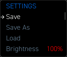
Press the Settings switch to open the Settings menu — a vertically scrolling list. Rotate to highlight, short press to activate.
Project settings: Tempo (numerical), Clock Source (Internal / USB Device / MIDI In / USB Host), Metronome (switch), CC On Layout Change (switch), Sensitivity (list), Brightness (numerical, 5–100).
Sub-screens: Velocity Curve -> Velocity Curve editor; Pedal Input A / B -> pedal input config; Routing -> routing matrix; CV Clock -> CV clock config.
Project management: Save, Save As, Load, Save Backup Project, Load Backup Project, Load Factory Project, Reset Demo.
Calibration: Encoder (read-only status indicator), CV (read-only status indicator), CV Gain (numerical), Run CV Calibration (button — launches calibration routine), Format SD Card & Reboot (button — opens confirmation dialog before formatting).
Tip: Numerical rows (Tempo, Brightness, CV Gain) enter edit mode on short press. Rotate to change the value, then short press again to confirm.
11.4 Arpeggiator Settings Screen
Reached from the element Mapping screen for a keyboard element with an arpeggiator.
| Parameter | Type | Description |
|---|---|---|
| Rate | List | Note division: 1/4, 1/8, 1/16, 1/32, etc. |
| Style | List | Pattern: Up, Down, Up-Down, Random, As Played, etc. |
| Octave | Numerical | Octave span (1–4) |
| Pressure | Numerical | Finger pressure -> velocity scaling (0–100%) |
| Quantize | Switch | Lock rate to project clock |
Changes take effect immediately. The title bar shows the element name.
11.5 Scale / Key Selector
Press the Scale switch to open the Scale panel, or trigger it from a SoloKey element configured for scale access. Three vertical panels:
- Scale (left half) — roller listing factory scales.
- Root Note (right quarter) — roller for chromatic root (
C–B). - Octave (right quarter) — roller for octave transposition (−2 to +8).
An optional Show Chromatic Notes toggle controls whether out-of-scale pitches appear on the surface.
Element-specific behaviour:
- ChromaKeyboard — the scale roller changes key coloring only; the chromatic layout remains available.
- DrumpadKeyboard — the Scale panel is hidden entirely; scale selection does not apply.
Tip: Use the Root Note and Octave rollers to transpose an Iso Keyboard quickly without editing the underlying layout in Erae Lab.
11.6 Info Screen (Status Overlay)
A transient overlay that appears automatically to communicate a firmware condition. Dismisses on timeout or any encoder input. Messages: No SD, Project Saved, Low Power, SD Error, SD Disk Error, Project Corrupted, Legacy Project Detected. On legacy project detection the overlay advises connecting Erae Lab to migrate the project — no migration option is provided on-device.
11.7 Routing Screen
Reached via Settings -> Routing. A matrix of on/off switches connecting MIDI sources to destinations for pass-through routing:
MIDI In -> USB Host, USB Device, MIDI Out A, MIDI Out B USB Device -> USB Host, MIDI Out A, MIDI Out B USB Host -> USB Device, MIDI Out A, MIDI Out B
Short press any switch to toggle. Settings are saved with the project.
Tip: Enabling MIDI In -> USB Device lets Erae 2 act as a MIDI merger between a hardware synth and your DAW without additional software.
11.8 MIDI Monitor
A diagnostic scrolling log of MIDI 2.0 messages generated in real time. Each row shows Time, Group / Channel, Type (NoteOn, NoteOff, PolyPressure, CC, PC, ChPressure, Pitchbend), and Value. The log holds the most recent 30 messages in a ring buffer. The monitor is read-only; use the Return switch to leave the screen.
11.9 CV Clock Screen
Reached via Settings -> CV Clock.
| Parameter | Type | Description |
|---|---|---|
| Enabled | Switch | Activates CV clock output |
| Beat Division | List | Pulse rate: 1/4, 1/8, 1/16, 1/24 (PPQN), 1/32, etc. |
| Clock Output | Numerical | CV jack for the clock pulse (1–4) |
| Reset Output | Read-only | Adjacent reset/sync output automatically paired with Clock Output |
Tip: Set Beat Division to
1/24and patch the Clock Output to a Eurorack module to synchronise at 24 PPQN.
Project Save and Load Screens
The project entries in Settings expose the current on-device project lifecycle:
- Save -- writes the current project to its existing SD identity when one exists.
- Save As -- opens the save screen so you can choose an existing project or create a new project name.
- Load -- opens the SD project list and loads the selected project.
- Save Backup Project -- writes the current state to flash backup/fallback storage.
- Load Backup Project -- loads the flash backup project. When an SD card is mounted, it is saved into the SD library as
Backup,Backup_2, and so on. - Load Factory Project -- loads the factory project into a temporary no-SD identity until you explicitly save it.
Factory and flash-backup projects have no SD project identity until saved. They are excluded from normal manifest/sync as editable SD projects until you use Save or Save As.
11.10 Pedal Input Configuration
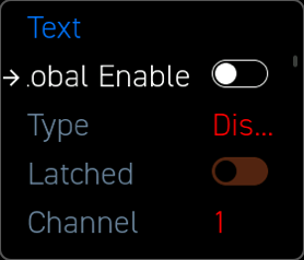
Reached via Settings -> Pedal Input A or Pedal Input B. Common parameters apply to every pedal type:
Global Enable (switch), Type (list: Disabled, Switch, Expressive, Sustain, Kick), Latched (switch — latching vs. momentary), Channel (list, 1–16), Out Routing (button -> Element Routing screen), Calibrate (button -> Calibration Wizard).
Type-specific parameters are shown or hidden automatically based on Type:
- Switch — Sends a message on press and on release. Four message types:
Note,CC,PC,Tap Tempo. Separate On and Off values for Note and CC types. - Expressive — Continuous CC or CV with optional Invert.
- Sustain — Sub-parameters: Mode (
Binary/Continuous), CC Number, On Value, Off Value. Binary mode sends CC on press and release using the configured On and Off values. Continuous mode tracks pedal position as CC or CV. - Kick — Sub-parameters: Note, Velocity Sensitivity, Note Duration (
25 ms/50 ms/100 ms/200 ms), Impact Threshold, optional CV Gate and CV Velocity outputs.
11.10.1 Format SD Card Confirmation Dialog
When Format SD Card & Reboot is selected from the Settings menu, a confirmation dialog (confirmation_lcd_view) appears before any action is taken. It presents two options:
- Yes — formats the SD card immediately and reboots the device.
- No — cancels and returns to the Settings menu.
This dialog prevents accidental data loss from an inadvertent menu selection.
11.10.2 Pedal Input Calibration Wizard
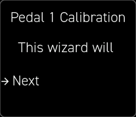
A stepped wizard capturing pedal travel range: Welcome -> Capture Min -> Capture Max -> Complete (or Failed if min and max are too close). For Kick mode, Capture Max is replaced by guided impact capture: light taps first (minimum 3), then strong kicks (minimum 3). Calibration is saved to flash on completion.
11.11 Velocity Curve Editor
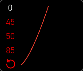
Reached via Settings -> Velocity Curve. A live curve graph shows how finger pressure maps to MIDI velocity. Four selectable parameters on the left:
| Parameter | Description |
|---|---|
| Threshold | Minimum pressure to register a touch |
| Drive | Gain applied to raw pressure before the curve |
| Compand | Expands or compresses dynamic range |
| Range | Maximum MIDI velocity at full pressure |
A Reset button restores factory defaults. The graph redraws live as parameters change.
Tip: High Threshold combined with moderate Drive makes the surface feel more like a traditional keyboard — intentional pressure required before notes register.
11.12 Element Routing Screen
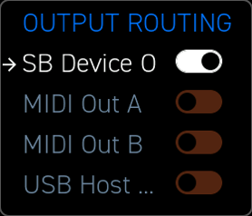
Controls which MIDI output ports receive data from the focused element. Reached from the Mapping screen or Pedal Input configuration.
To USB Device, To MIDI A, To MIDI B, To USB Host — all can be enabled simultaneously. Changes apply immediately.
11.13 Mapping Screen
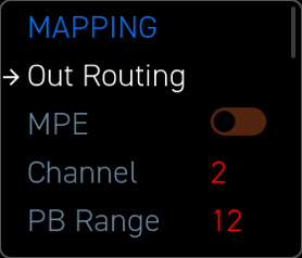
Opened for the focused element when editing its on-device parameters. The title shows element name and type. Parameters vary by type:
- Button — note, velocity, CC number, CC on/off values, channel.
- Fader 1D / 2D — CC assignments, default values, center values, min/max, response curve; 2D adds separate X and Y controls.
- SoloKey — note, channel, latch. Opens the Scale panel when configured; scales are also accessible from SoloKey elements.
- Keyboard — MIDI channel, transpose, CV assignments (Pitch, Gate, optional expression outputs). CV Num Voice and base channel assignment appear here for keyboard elements.
A MIDI Routing button at the bottom links directly to the Element Routing screen for that element.
11.14 Looper Settings Screen
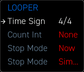
Reached from the Home screen looper controls.
| Parameter | Current Value | Description |
|---|---|---|
| Time Signature | 4/4 only | Bar length calculations for the looper display |
| Count In | None only | Bars before recording starts — count-in is not currently implemented |
| Stop Mode | Now only | Looper stops immediately on Stop command |
| Loop View | Simple only | Looper arc display style |
Note: Additional options for Time Signature, Count In, Stop Mode, and Loop View are planned for future firmware releases. Current firmware supports the values listed above.
11.15 Save / Save As / Load Screens
Save writes the current project to its existing SD identity when one exists. Save As lists SD card project files and lets you choose an existing project or create a new project name. The active project is marked with *. Use the Return switch to cancel.
While saving, a full-screen animated overlay cycles through Saving -> Saving. -> Saving.. -> Saving... at 500 ms intervals. The encoder is unresponsive until the write completes. The Info screen then briefly confirms with Project Saved.
Load presents the SD project list. Short-pressing a project loads it immediately, replacing the current project in RAM.
Tip: Before loading a project, use Save, Save As, or Save Backup Project to preserve your current work. Loading cannot be undone from the LCD.
Chapter 12 — Switches & Encoder
Erae 2 gives you direct physical control through 18 labeled panel switches with LED indicators, a dedicated Calibrate switch (no LED), an encoder (with shaft click), and dedicated function buttons — all arranged around the LCD. These controls let you navigate menus, change settings, and trigger functions without touching the performance surface.
The Panel Switches
The Erae 2 panel provides 18 capacitive touch switches with LED indicators, plus the Calibrate switch (no LED). The encoder shaft also functions as a click input (ADC-based, not capacitive).
Numbered Switches (N1–N8)
Eight general-purpose switches labeled N1 through N8 occupy the top row. These are programmable and serve as layout selectors, mute buttons, or custom triggers depending on your project configuration.
Tip: Assign N1–N8 to jump directly to your most-used layouts — a single tap switches your entire playing surface instantly.
Function Switches
The remaining ten switches (with LEDs) have dedicated roles, plus the Calibrate switch (no LED):
| Switch | LED | Function |
|---|---|---|
| Play/Rec | Yes | Start or arm the looper; begins recording on the first touch |
| Stop | Yes | Stop playback and return the looper to the beginning |
| Plus | Yes | Increment the selected value or navigate forward in lists |
| Minus | Yes | Decrement the selected value or navigate back in lists |
| Scale | Yes | Open the scale selection menu |
| Mapping | Yes | Open the element mapping overlay |
| Arp | Yes | Toggle the arpeggiator on or off |
| Settings | Yes | Open the Settings screen |
| Return | Yes | Go back to the previous screen, or back to Home from Settings |
| Calibrate | No | Initiate a touch surface FSR calibration pass |
Tip: The Return switch always brings you back — press it from any nested menu to step up one level, or hold it briefly to jump directly to the Home screen.
The Encoder
Erae 2 features a single rotary encoder (Main Encoder) located beside the LCD. It is the primary control for navigating menus and entering values.
Scroll
Rotate the encoder to scroll through list items, adjust numerical parameters, or step between items on screen. Each physical detent moves exactly one step — the encoder does not accelerate. This ensures precise, predictable control at all speeds.
Tip: For parameters with a large range such as Tempo (1–999 BPM), use the Plus and Minus panel switches for larger increments, then fine-tune with the encoder for single-step precision.
Click
Press the encoder shaft inward to confirm the currently highlighted selection. In a list, this chooses the item. On a numeric field, this commits the entered value and moves focus to the next field. The encoder click is an ADC-based input, distinct from the capacitive panel switches.
Return Switch
The Return switch acts as the Return / Home control in all navigation contexts. One press from any Settings sub-page returns to the parent screen. Pressing Return from the top-level Settings screen returns to the Home view, which shows the active layout name, looper status, and current tempo.
Shift Combinations
Holding certain switches while pressing others unlocks secondary functions. Available combinations depend on the active screen:
- Plus + Minus (simultaneous, hold) — Reset the focused parameter to its factory default value.
- Play/Rec + Stop (simultaneous) — Clear the current looper record buffer.
Tip: While holding the Settings switch, contextual shift hints appear on the LCD so you can discover available combinations in context.
Chapter 13 — LED Feedback
The Erae 2 surface is covered by a 42 × 24 grid of full-color RGB LEDs — 1,008 individually addressable pixels that bring your layouts to life. Every element type has its own visual language, and touch interactions produce immediate feedback so you always know the surface is responding.
The RGB Color System
Each LED outputs 8-bit color per channel (red, green, blue), giving a palette of over 16 million colors. The firmware applies a per-channel intensity calibration curve to the physical hardware: the red channel peaks at 70 % of its nominal maximum, green at 100 %, and blue at 65 %. This calibration ensures that colors defined in Erae Lab appear natural and consistent on the surface — a pure white in the editor looks truly white on the hardware, not blue-shifted.
Overall LED brightness is capped at 80 % of the hardware maximum to prevent thermal stress during extended sessions.
Tip: Colors you set in Erae Lab are what you see on the hardware. The calibration is built into the firmware — you do not need to adjust anything manually.
Brightness Control
Global brightness is adjustable from the Settings screen. Reducing brightness is useful in dark studio environments or when running from battery-powered rigs where power draw matters.
Per-Element Visualization
Each element type uses a distinct visual style. Styles are assigned in Erae Lab and stored in the project.
Keys
Key elements display a solid color or gradient that covers their geometry. Scale-aware layouts use edge color styling: in-scale notes show a brightly colored border with a darker fill, while out-of-scale notes appear dimmer or use an alternate color. Root notes are typically highlighted with a distinct hue.
Style options include:
- Solid Color — Uniform fill across the entire key area
- Linear Gradient — Color fades from one hue to another across the key
- Circular Gradient — Color radiates outward from the center of the key
- Rectangular Gradient — Color fades from the center to the edges
- Edge Color — Distinct border color with a contrasting fill
- Image / Compressed Image — Custom bitmap rendered on the key surface
Buttons
Buttons use dual-intensity or dual-color styles to communicate their on/off state. When the button is off, the LED shows a reduced-intensity version of the assigned color (or a distinct "off" color). When active, the LED lights at full brightness. Latched buttons hold their lit state between presses.
Faders (1D and 2D)
Fader elements display a bar or active area of light that tracks your finger position. The fill starts at the fader's Center Value and extends to the current value. Newly created faders use a center value of 0, which matches the traditional from-minimum rendering; setting the center to 63 creates a center-detent visual response.
- Fader 1D — A vertical or horizontal bar fills from the center value toward your touch point. With center
0, it fills from the bottom/minimum end. With center63, it fills away from the middle in either direction. - Fader 2D — A crosshair or dot marks your X/Y position within the element area. The active area is drawn between the center point and the current position, and a dim center crosshair can remain visible as a reference for center-detent XY layouts.
API Zone
API zones have no built-in visual style — the color of each pixel is driven entirely by your software through the API, allowing fully custom visualizations.
Animations
Animations layer dynamic visual effects on top of the base element style. They are configured per-element in Erae Lab and play in response to touch events.
Three animation trigger points are available:
| Trigger | When it fires |
|---|---|
| Click | Immediately when the finger first contacts the surface |
| Slide | Continuously while the finger moves across the surface |
| Release | When the finger lifts off |
FingerGlow
A radial bloom of light trails behind the moving finger. The glow follows the finger's path across the element, leaving a brief luminous trail that fades naturally. Color, shape (round or rectangular), speed, and coloring mode (fixed or matching the element color) are configurable.
Tip: A fast click FingerGlow with a contrasting color gives playing keys a piano-like hammer effect — subtle but noticeable in live performance.
Ripple
A ring of light expands outward from the touch point, fading as it travels away from the contact. Ripples give percussion and rhythm elements a physical, drum-pad feel.
Halo
A static radial bloom appears at the contact point and stays fixed there for the duration of the touch — it does not trail the finger. The Halo is useful for sustaining keys, where you want a persistent glow under each held note rather than a moving effect.
ColorMorph
On press or release, the element transitions between two configured colors over a configurable duration and intensity. Intensity controls how much the color changes; Speed controls the transition time. ColorMorph can be set to trigger on Click (finger-down), Release (finger-up), or both.
Tip: Use ColorMorph on a fader element — set a warm color for pressed state and a cool color for released state, making the active fader position visually distinct at a glance.
Press Feedback
When you touch any active element, the LED responds immediately in two ways:
-
Intensity shift — The element brightens or dims according to the
hoverIntensitysetting. Elements set to a positive intensity increase appear brighter under your finger; negative values produce a dimming effect. This confirms that the surface has detected your touch before any MIDI is sent. -
Animation trigger — If the element has a click animation, it fires at the same moment as the intensity shift.
Tip: The press feedback is independent of MIDI output — it fires on raw touch detection, so you'll always see confirmation even if MIDI routing is being reconfigured.
Status Indicators
The LCD and switch LEDs carry additional status information that does not appear on the main surface grid.
Loading Spinner
While a project is loading or a sync operation is running, a spinner animation plays on the LCD. The main LED surface remains lit with the previous layout during loading to avoid a dark-screen moment.
Saving Flash
When a project save completes, the Project Saved confirmation appears on the LCD. A brief full-surface flash may accompany the save on older firmware.
Clock Sync Pulse
When an external MIDI clock source is selected (USB-dev, MIDI, or USB-host), the clock lock state is reflected in the Home screen's tempo display. The BPM readout updates in real time as the incoming clock is averaged and filtered.
Tip: If the BPM display fluctuates rapidly, the incoming MIDI clock may be jittery. Switch the clock source to
INTto stabilize tempo while troubleshooting.
Switch LEDs
18 of the panel switches have their own LED indicator (the Calibrate switch and encoder click have no LED). These reflect:
- Active layout — N1–N8 LEDs highlight whichever layout slot is currently loaded
- Function state — Arp and other active function switches light when their features are active
- Navigation position — The active menu item is indicated by the corresponding switch LED
Tip: The switch LED brightness tracks global brightness — reducing brightness in Settings dims both the surface grid and the switch panel together.
Chapter 14 — Connecting to Erae Lab
Erae Lab is the companion desktop application for designing, editing, and managing your Erae 2 projects. Connecting the hardware to Erae Lab unlocks project editing, firmware updates, and background project sync.
USB Connection
Connect Erae 2 to your computer using the included USB cable. The device appears as a USB composite device. Erae Lab communicates with the device over a Vendor USB channel — a dedicated, low-latency communication path that is separate from the MIDI ports. You do not need to configure any MIDI port to use Erae Lab.
Erae Lab detects the connected device automatically — no driver installation is required on macOS or Windows. When detection succeeds, the connection indicator in the Erae Lab toolbar turns green and shows the detected device model (Erae or Erae 2) and firmware version.
Auto-Detection
Erae Lab polls for connected devices on a timer. When the device is found, the following handshake occurs automatically over the Vendor USB channel:
- Lab identifies the device via USB Product ID (Erae 2:
0xDF02/0xDF03; Erae:0xDF00/0xDF04). - Lab requests the firmware version and device unique ID.
- Lab requests the device status (power OK, media card present, active project).
- Lab initiates a project manifest request to compare the device's stored projects with the Lab library.
The entire handshake completes in under two seconds on a healthy connection.
Tip: If auto-detection does not trigger, disconnect and reconnect the USB cable, then use Erae Lab's device/reset connection action to force a fresh scan.
Connection Indicators
Once connected, both Erae Lab and the device LCD provide feedback:
- Erae Lab toolbar — Shows a green dot and the device firmware version.
- Erae 2 LCD — Displays a sync animation while the manifest exchange is in progress, then returns to the Home view.
- Lab status — Shows progress during active sync or firmware operations, and connected/idle state when complete.
Tip: The sync indicator in the Erae Lab toolbar also shows a spinner during firmware updates and file transfers. Wait for the spinner to stop before disconnecting.
Project Sync
Erae Lab and Erae 2 share a background sync/session link. Layout edits in Lab autosave and flow to the device after the edit settles; device-side project changes are reported back to Lab through the same session. Users normally should not run a manual push/pull step after every edit.
Note: Global settings — Brightness, Sensitivity, and Velocity Curve — are device-wide preferences and do not participate in project sync. They are not pushed or pulled with project data.
Conflict Resolution
If both Lab and the device show changes to the same project, Lab presents conflict choices. You can choose to:
- Keep Lab — use the Lab copy and send it to the device.
- Keep Device — use the device copy and pull it into Lab.
- Keep Both — keep Lab's version and import the device version as a separate copy.
Tip: To avoid conflicts, always connect your Erae 2 before editing in Erae Lab. Live editing with the device connected eliminates the need to resolve conflicts later.
Firmware Updates via Erae Lab
Firmware updates are delivered through Erae Lab. Erae Lab includes bundled firmware and can update a normal device or recover a device that is already in bootloader mode.
To update:
- Open Erae Lab with the device connected.
- Erae Lab detects the current firmware version and offers the bundled update when needed.
- Confirm the update. The device reboots into bootloader mode.
- Erae Lab streams the
.syxfirmware image over MIDI SysEx. Do not disconnect the USB cable during transfer. - The device reboots automatically into the new firmware.
If Erae Lab detects an orphan bootloader, it offers recovery choices: install the latest bundled firmware, select a firmware file manually, or dismiss the prompt.
Tip: Firmware updates do not erase your projects. Projects are stored separately from the firmware image and are not touched during the firmware update process.
What Requires Erae Lab vs. Standalone
Erae 2 is fully functional without Erae Lab connected. The following table summarises which features require Lab:
| Feature | Standalone | Requires Lab |
|---|---|---|
| Playing layouts | Yes | No |
| Switching layouts (N1–N8) | Yes | No |
| Adjusting tempo and clock | Yes | No |
| Pedal Input and CV configuration | Yes (LCD Settings) | For advanced editing |
| Editing element tuning and MIDI mapping | Yes (LCD Mapping, Scale, and Routing screens) | For advanced editing |
| Moving, resizing, styling, or changing element types | No | Yes |
| Creating new layouts | No | Yes |
| Firmware updates | No | Via Erae Lab |
| Exporting/importing project files | No | Yes |
Tip: You can save the current state from the device's Settings screen even when Erae Lab is not connected, so your performance edits (tempo, routing) are never lost between sessions.
See the Erae Lab User Manual, Chapter 12 for detailed sync operations.
Chapter 15 — Settings
The Settings screen is your on-device control centre for global preferences, project configuration, project save/load, MIDI routing, CV clock, and hardware calibration. Press the Settings switch to open it from any screen.
Global Settings
Brightness
Brightness controls the overall LED intensity of the surface and switch panel together. Rotate the encoder to set a value from 5 (minimum, always-on dim glow) to 100 (maximum). Lower values reduce power draw and are easier on the eyes in dark environments.
Tip: A brightness setting around 60–70 % is comfortable for most live performance environments. Reserve maximum brightness for installations or well-lit stages.
Sensitivity
Sensitivity sets how responsive the surface is to touch. Four preset options are available:
| Option | Description |
|---|---|
XSensitive | Most responsive — ideal for studio use or players with a very light touch |
Sensitive | Responsive, with some protection against accidental triggers |
Safe | Default — balanced for most playing styles and environments |
XSafe | Least responsive — reduces false triggers in high-vibration environments |
Tip: If the surface feels unresponsive or requires excessive pressure, switch to
XSensitive. If ghost notes appear without being touched, switch toSafeorXSafe.
Velocity Curve
Press Velocity Curve to open the velocity curve editor. Four parameters shape the response:
- Threshold — The minimum pressure required to register a note. Raise this to reduce accidental triggers on a light touch.
- Drive — Amplifies the velocity signal for the middle of the pressure range.
- Compand — Applies compression/expansion to the velocity curve, making dynamics easier or harder to control.
- Range — Sets the maximum velocity output value (MIDI 0–127).
A live curve preview renders on the LCD as you adjust each parameter. Press the reset button to return all four values to factory defaults.
Tip: If your playing feels too dynamic and notes are always at maximum velocity, lower Drive and raise Threshold slightly. If all notes feel soft, raise Drive and lower Threshold.
Project Settings
The current Settings list includes Save, Save As, Load, Brightness, Sensitivity, Tempo, Clock Source, Metronome, CC On Layout Change, Velocity Curve, Pedal A/B, Routing, CV Clock, Save Backup Project, Load Backup Project, Load Factory Project, CV Gain, Run CV Calibration, MIDI 2.0: ON/OFF, Format SD Card & Reboot, and Reset Demo when demo mode is active.
Tempo
Tempo sets the internal BPM for the looper, arpeggiator, and metronome. Range: 1–999 BPM. Rotate the encoder to adjust; the change takes effect immediately.
Clock Source
Clock Source selects the timing reference:
| Value | Description |
|---|---|
INT | Internal clock — device generates its own tempo |
USB-dev | Sync to MIDI clock received on the USB Device port |
MIDI | Sync to MIDI clock received on the MIDI input |
USB-host | Sync to MIDI clock from a connected USB Host device |
Tip: When using a DAW as the clock master, set Clock Source to
USB-dev. Erae 2 will lock its clocked performance features to the DAW's transport.
Metronome
The Metronome toggle enables an audible click output that follows the current tempo and clock source. The click is sent as a MIDI note on the configured routing.
CC on Layout Change
When CC on Layout Change is enabled, a MIDI Control Change message is sent whenever you switch the active layout using N1–N8. This allows external software to follow layout changes automatically.
MIDI Routing
Press MIDI Routing to open the routing matrix. Each routing toggle connects a MIDI input to one or more outputs:
| Route | Description |
|---|---|
| MIDI In -> USB Host | Forward MIDI input to the USB Host output |
| MIDI In -> USB Device | Forward MIDI input to the USB Device output |
| MIDI In -> MIDI Out A | Thru: MIDI in to MIDI out A |
| MIDI In -> MIDI Out B | Thru: MIDI in to MIDI out B |
| USB Device -> USB Host | Route USB Device input to USB Host output |
| USB Device -> MIDI Out A | Route USB Device input to MIDI out A |
| USB Device -> MIDI Out B | Route USB Device input to MIDI out B |
| USB Host -> USB Device | Route USB Host input to USB Device output |
| USB Host -> MIDI Out A | Route USB Host input to MIDI out A |
| USB Host -> MIDI Out B | Route USB Host input to MIDI out B |
Tip: To use Erae 2 as a MIDI thru box, enable MIDI In -> MIDI Out A and connect your upstream controller to MIDI In and your synth to MIDI Out A.
CV Clock Output
CV Clock configures a CV gate pulse output synchronized to the internal tempo. Enable the clock, choose the CV output index, and set the beat division:
| Division | Description |
|---|---|
1 ppqn | One pulse per quarter note |
2 ppqn | Two pulses per quarter note |
4 ppqn | Four pulses per quarter note (sixteenth notes) |
8 ppqn | Eight pulses per quarter note |
24 ppqn | Standard MIDI clock rate |
48 ppqn | Double-speed MIDI clock rate |
The reset output is read-only and automatically paired with the adjacent output after the selected clock output. It cannot currently be disabled or independently assigned.
Pedal Input Configuration
Erae 2 has two pedal inputs (Pedal A and Pedal B). The LCD currently labels these as FootSw A and FootSw B; this label will be updated to Pedal A / Pedal B in a future firmware release. Press the corresponding entry in Settings to open the individual configuration page.
Type
Type selects the pedal behavior mode:
| Type | Best for |
|---|---|
Disabled | Input ignored |
Switch | On/off switch pedal, sends Note or CC/PC on press/release |
Expressive | High-resolution continuous pedal with inverted option |
Sustain Binary | Standard sustain pedal — sends CC64 on/off |
Sustain Continuous | Expression pedal — sends continuous CC |
Kick | Velocity-sensitive kick trigger (drum machine pedal) |
Global Enable
Toggle Global Enable to activate or bypass the pedal input without losing its configuration.
Routing
Out Routing selects which MIDI output port carries the pedal input messages.
Latched
When Latched is enabled (Switch and Sustain Binary types), a single press toggles the output state rather than requiring the pedal to be held.
Channel
Channel sets the MIDI channel (1–16) for pedal input messages.
Tip: Assign Pedal Input A to sustain and Pedal Input B to expression for a keyboard-like playing setup without reconfiguring between projects.
Calibration Procedures
CV Calibration
Press CV Calibration to open the CV output calibration sub-screen, then press Run CV calib to start the automated procedure. The firmware drives each of the 24 CV outputs through a known voltage range and measures the result. Adjust CV Gain if the output voltages read consistently high or low on a reference meter.
Encoder Calibration
Press Encoder Calibration to re-initialize the encoder detent positions. Use this if the encoder feels sticky, skips steps, or registers events in the wrong direction.
Pedal Input Calibration
For expression-type pedals (Sustain Continuous, Expressive), accurate calibration is essential. Press Calibrate at the bottom of the Pedal Input configuration page to launch the calibration wizard.
The wizard guides you through three steps for most pedal types:
- Welcome — Confirms the pedal input index and pedal type being calibrated.
- Capture Min — Press the pedal fully released; confirm to record the minimum position.
- Capture Max — Press the pedal fully depressed; confirm to record the maximum position.
For Kick pedals, the wizard instead captures:
- Light Taps — Strike the pedal lightly at least three times to set the soft-strike reference.
- Strong Kicks — Strike the pedal hard at least three times to set the hard-strike reference.
The wizard then computes the calibration and saves the result to flash. If the pedal values are out of range or the required number of strikes was not captured, the wizard reports a failure and lets you retry.
Tip: Always calibrate a new pedal input before your first performance. Pedals vary significantly in their physical travel range, and an uncalibrated pedal may clip at min or max before reaching its physical limits.
Project Management
- Save — Write the current project to its existing SD identity when it has one.
- Save As — Save under a new or selected project name.
- Load — Browse and load a project from the SD card project library.
- Save Backup Project — Write the current project to the internal flash backup slot.
- Load Backup Project — Restore the project from the internal backup slot. With SD mounted, it is saved into the SD library as
Backup,Backup_2, and so on. - Load Factory Project — Load the factory default project as a temporary project until you explicitly save it.
- Format SD Card & Reboot — Erase and reformat the SD card, then reboot. Use only to recover from SD errors.
- Reset Demo — Restore all factory demo content.
Factory and backup projects have no SD identity until saved. They are excluded from normal manifest/sync as editable SD projects until Save or Save As gives them an SD-backed project identity. Project rename/delete are Lab/vendor-protocol operations and are not exposed as standalone LCD actions.
Storage States and Recovery
Erae 2 saved projects normally live on the SD card. Flash storage is used for backup/fallback data, global calibration, and device metadata.
- Mounted SD -- normal project save/load and Lab sync are available.
- No SD -- the device can use factory or backup fallback state, but it cannot save/load the normal SD project library.
- No filesystem -- the device prompts for formatting before the SD can be used.
- Disk/read-write failure -- save/load may fail; format or replace the SD card.
- Health-check failure -- treat the SD as unreliable and back up/reformat or replace it.
Project writes are crash-safe. If power is interrupted during a write, the firmware attempts to recover the last valid project data on the next boot. Formatting the SD card erases SD projects and reboots the device.
Chapter 16 — Troubleshooting
This chapter covers the most common issues you may encounter with Erae 2 and how to resolve them.
Connection Issues
USB Not Recognized by Erae Lab
Symptoms: Erae Lab shows no connected device; the toolbar indicator stays grey.
Steps:
- Check that the USB cable supports data transfer (not a charge-only cable). Try a different cable.
- Ensure the cable is plugged into the correct port on Erae 2 (the rear data/power USB-C port).
- In Erae Lab, open Preferences and click Reset MIDI Connections. This forces a fresh device scan.
- On Linux, USB device access may be blocked by udev rules. Check that your user has permission to access the device node (usually
/dev/bus/usb/...). Add a udev rule for Vendor ID0x2B87if needed. - Restart Erae Lab with the device already connected.
Tip: If Erae Lab previously worked and stopped recognizing the device after a system update, the USB class driver may have changed. Reinstall Erae Lab to restore the correct driver configuration.
MIDI Ports Not Appearing in DAW
Symptoms: Erae 2 is connected but its MIDI ports do not show up in your DAW's MIDI device list.
Steps:
- Confirm the device is connected and recognized by Erae Lab first (green indicator). MIDI ports are registered at the OS level immediately on connection.
- On macOS, check Audio MIDI Setup (Applications -> Utilities) — Erae 2 should appear in the MIDI Studio window.
- On Windows, check Device Manager for the MIDI device listing. Confirm no yellow warning icons are present.
- Restart your DAW with Erae 2 already connected. Some DAWs only scan for MIDI ports at startup.
- Verify the device is in normal MIDI 1.0 USB mode unless you intentionally enabled MIDI 2.0 in Settings. Changing MIDI 2.0: ON/OFF requires a reboot.
Tip: In normal mode, Erae 2 exposes
Erae 2 MIDI(standard) andErae 2 MIDI (MPE)(expressive play). Do not route a MIDI 2.0 cable manually unless instructed by a specific workflow.
MPE Port Not Appearing on macOS (Stale Device Entry)
Symptoms: The Erae 2 MIDI (MPE) cable does not appear in your DAW on macOS, or it appears with wrong port numbering, after a firmware update or reconnect.
Steps:
- Open Audio MIDI Setup (Applications -> Utilities -> Audio MIDI Setup).
- Click Window -> Show MIDI Studio if the MIDI Studio window is not visible.
- Locate any stale Erae 2 device entry (it may appear greyed out or show an older name).
- Right-click the stale entry and choose Remove Device.
- Disconnect and reconnect the USB cable. The device will re-enumerate and the expected MIDI ports will appear.
- Restart your DAW to pick up the refreshed port list.
MIDI Routing Problems
Notes Not Sounding on Expected Output
Steps:
- Check the element's MIDI Output Destination in Erae Lab (Main, MPE, or USB Host).
- Verify the MIDI routing matrix in Settings -> MIDI Routing does not create an unintended loop or block.
- Confirm the MIDI channel matches your synth or DAW track.
- For MPE instruments, ensure Erae 2 is set to MPE mode and the receiving instrument has MPE enabled. Point your DAW track at the
Erae 2 MIDI (MPE)cable.
Unexpected Notes or Double Triggers
Symptoms: Notes sound twice, or notes appear without touching the surface.
Steps:
- Check MIDI Routing for enabled thru routes (e.g., MIDI In -> USB Device). A thru route combined with a DAW echo setting can cause note doubling.
- If ghost triggers occur in a specific region, check the Sensitivity setting in Settings. Switch to
SafeorXSafeto reduce false triggers.
Touch Feels Unresponsive
Symptoms: Notes require heavy pressure to trigger, or velocity values are consistently low.
Steps:
- In Settings, set Sensitivity to
XSensitivefor maximum surface responsiveness. - Open Velocity Curve and adjust the Drive and Range parameters toward faster attack — lower the Threshold slightly if notes require too much pressure.
- Inspect the surface for debris or condensation. Clean with a dry lint-free cloth.
- Ensure the device has been powered on for at least two minutes before playing — sensor baselines settle slightly with temperature.
LED Not Responding
Surface LEDs Are Dark or Partially Lit
Steps:
- Check Brightness in Settings — it may be set to a low value (minimum is 5).
- Verify the active layout has elements with non-black colors assigned. An empty layout with no elements will show a dark surface.
- If a region of the grid is dark but surrounding areas are lit, the LED controller for that zone may be in a fault state. Power-cycle the device (disconnect USB, wait five seconds, reconnect).
- A full factory reset (see below) can recover from corrupted LED configuration state.
Tip: A brief dark flash during a project load is normal — the surface blanks momentarily while the new layout's LED data is computed.
Factory, Backup, and Reset Procedures
Load Factory Project loads the factory project as a temporary project. Your projects stored on the SD card are not erased, and the factory project does not become part of the SD library until you save it.
- From the Settings screen, press Load Factory Project.
- Confirm the prompt on the LCD.
- The device reloads with factory defaults.
Save Backup Project writes the current state to flash backup storage. Load Backup Project restores that backup; with SD mounted, it saves as Backup, Backup_2, and so on.
Reset Demo restores factory demo content when demo mode is active. Use Format SD Card & Reboot only when you intentionally want to erase SD projects and recover from storage problems.
Bootloader Recovery
If the device fails to boot (LCD remains dark, no switch LEDs, no USB enumeration), the firmware may be corrupted. Use bootloader recovery to reflash:
- Connect the device to the computer and open Erae Lab.
- If Erae Lab detects a bootloader device, choose Install latest firmware or Select firmware file.
- Erae Lab streams the
.syxfirmware over MIDI SysEx. Do not disconnect USB during transfer. - The device reboots automatically into the new firmware.
Tip: Keep a copy of the latest firmware file saved locally. If the bundled firmware is unavailable, use Erae Lab's select-file recovery option.
Orphan Bootloader Detection
If the firmware crashes during an update (e.g., due to a power interruption), the device may reboot into the bootloader and stay there. Erae Lab detects this state automatically: when a device enumerates as a bootloader rather than a normal Erae 2, Erae Lab displays recovery choices to install the latest firmware, select a firmware file, or dismiss.
Tip: To prevent bootloader orphaning, always use a quality USB cable and avoid power-cycling the device during a firmware update. If it does occur, the recovery procedure above will always restore the device to normal operation.
SD Card Errors
FAT32 is the recommended filesystem for the SD card. If errors persist after reinsertion, use Format SD Card from Settings to reformat. If problems continue, try a different microSD card.
Saved projects normally live on the SD card. Without SD, the device can use factory or backup fallback state but cannot save/load the normal project library or dirty-sync those temporary projects to Lab until they are saved to SD.
The LCD may display one of the following SD card error messages:
| Message | Meaning | Action |
|---|---|---|
| No SD | No media card detected | Insert a compatible microSD card (FAT32, up to 32 GB) |
| SD Error | Filesystem not recognized | Format the SD card from Settings or use a computer |
| SD Disk Error | Read/write failure | Try Format SD Card from Settings; if it persists, replace the card |
| Project Corrupted | Project file is unreadable | Load Backup Project or Load Factory Project |
| Legacy Project Detected | Project from older firmware version | Erae Lab will migrate it on the next sync |
Tip: If the SD card is repeatedly not detected after reinsertion, power-cycle the device. The SD slot requires a clean power cycle to reinitialize after certain error states.
Known Issues
- Looper display shows layout number instead of loop position. The looper indicator on the LCD currently shows the active layout number rather than the loop playback position. This is a known display bug and will be corrected in a future firmware update.
Contacting Support
If you have followed the steps above and the problem persists, contact Embodme support:
Email: support@embodme.com
Please include your firmware version (visible in Erae Lab), a description of the issue, and the steps you have already tried.
Chapter 17 — Erae Compatibility
This chapter is a reference for users of the original Erae. If you own an Erae 2, most of this chapter does not apply to you — see the table at the end for a side-by-side comparison.
What Is Erae?
Erae is the first-generation hardware. It shares the same core surface and MIDI engine as Erae 2 but differs in several important ways: it has no LCD screen, no encoder, no CV outputs, and no pedal inputs. Navigation is entirely through five dedicated physical buttons and the LED surface. The Erae firmware target receives the same layout, arpeggiator, pattern, and looper features as Erae 2, within the constraints of its hardware.
Single Project
Erae operates with a single active project at all times. There is no project browser or project-switching UI. When the device powers on, it loads the project stored in its QSPI flash. All edits to layouts are saved automatically to that project after a short debounce period (approximately 10 seconds of inactivity following a change).
Project data is stored in a 128 KB region of internal flash (0x08100000) as a serialized binary. Up to 16 named projects (project_1 through project_16) can exist on the QSPI filesystem and be transferred to or from the device via Erae Lab.
Tip: Because Erae has no project browser on-device, use Erae Lab to back up your project before making large layout changes. Lab can pull the current project and save it to your computer.
32 Layouts and the Alt Mechanism
Erae supports 32 layouts arranged as 16 Main/Alt pairs. This doubles the effective number of layouts compared to Erae 2's 8 layouts.
- Layouts 0–15 are Main layouts. These are the layouts you see in the 4×4 layout selector grid.
- Layouts 16–31 are Alt layouts. Each Alt layout is paired with the Main layout of the same index: Alt layout 16 pairs with Main layout 0, Alt layout 17 pairs with Main layout 1, and so on.
Pressing the Alt button toggles the active layout between its Main variant and its corresponding Alt variant. The LED surface immediately reflects the new layout. This allows you to set up, for example, a chromatic keyboard as your Main layout and a drum pad as its Alt, switching between them instantly with a single button press.
Tip: Alt pairs are ideal for pairing a melodic layout with a rhythmic or percussive counterpart. You always stay in context — Plus/Minus still adjusts octave on the active layout whichever variant is showing.
The 5-Button Navigation System
Erae has five dedicated physical buttons. There is no touchscreen, no encoder, and no soft buttons. All navigation happens through these five buttons and the LED surface.
Home
- Single press: Toggles the layout selector. The LED surface displays a 4×4 grid of your 16 Main layouts. Touch any cell to switch to that layout.
- Double long-press: Enters sleep mode. The LEDs dim and touch input is suspended until a button is pressed.
- In any overlay view: Exits back to the active layout.
Alt
- Single press: Toggles between the Main and Alt variant of the current layout (see above).
- Hold: Opens the arpeggiator settings screen. The LED surface displays four quadrants for Rate, Style, Octave, and Pressure (pressure-to-velocity percentage). Use Plus/Minus to navigate between parameters and touch the corresponding quadrant to adjust the value. Press Home to exit.
Tip: You can use Alt hold to tune the arpeggiator in real time during a performance without interrupting MIDI output.
Scale (Fa)
- Single press: Opens the scale selector if the active layout contains a scale-selectable keyboard element. Touch the LED surface to choose a root note and mode.
- Short hold: Highlights the currently focused layout element on the LED surface.
- Long hold (45 frames, ~3 seconds): Opens CC mapping mode if the active layout contains a CC-mappable keyboard element. Allows you to reassign which MIDI CC each element sends.
Plus
- Single press: Transposes the active keyboard element one octave up.
- Plus + Minus simultaneously: Resets the octave to the base position.
- Plus + Home + Alt simultaneously: Runs the all-white LED check (diagnostic).
Minus
- Single press: Transposes the active keyboard element one octave down.
- Minus + Home simultaneously: Enters auto-calibration mode (recalibrates FSR thresholds).
- Minus + Alt simultaneously: Enters ghost-note removal mode.
Tip: Octave transpose applies per-layout. Switching layouts resets to that layout's saved octave position.
Z-Only Pressure Sensing
The Erae sensor reads Z only — vertical pressure at each cell. There is no per-touch X or Y position sensing at the sensor level. The constant kNumFSRDimension = 1 in the firmware confirms this: each FSR cell reports a single scalar value.
Finger position (X/Y on the surface) is computed by the firmware from the pressure distribution across the 42×25 sensor grid (1050 cells), using a center-of-mass algorithm across neighboring cells. This approach gives accurate X/Y coordinates for finger tracking but means that XY resolution depends on the pressure pattern spreading across multiple cells, not on dedicated per-axis sensors as in Erae 2.
Practical implications:
- Velocity is derived from the rate of Z change at the moment of contact, giving natural velocity response comparable to Erae 2.
- Aftertouch (channel pressure or poly pressure) works as expected and is fully functional.
- Pitch bend and slide work by tracking the computed X/Y position from the pressure distribution. Response is accurate but may feel slightly different from Erae 2 under very light touch, where the pressure spread across fewer cells reduces positional accuracy.
Tip: For the most accurate slide and pitch bend response, use a confident, full-contact finger press. Very light or fingertip-only touches may reduce X/Y tracking precision.
No LCD
Erae has no LCD screen. All status information is conveyed through LED patterns on the 42×25 RGB LED surface. Key status messages shown via LED:
| Condition | LED Indication |
|---|---|
| Project saved | Brief full-surface flash |
| Project loading | Animated pattern |
| QSPI error | Error pattern |
| QSPI not detected | Distinct error pattern |
| Project corrupted (factory loaded) | Warning pattern |
There is no settings menu accessible on-device. Global settings — including LED brightness, FSR detection threshold, FSR detection maximum, global sensitivity, and velocity curve — are configured through Erae Lab and stored in the device.
Tip: If you need to confirm the firmware version or check device status, connect to Erae Lab. The Lab displays firmware version, storage status, and device health in its sidebar.
No CV Outputs
Erae has no CV outputs. Erae 2's 24 CV channels, pitch/gate routing, and CV calibration system are entirely absent. There are no CV-related settings in the Erae project or global settings structures. If your setup requires CV/gate output, Erae 2 is required.
MIDI output from Erae is available on:
- USB Device (Main) — standard MIDI
- USB Device (MPE) — MPE MIDI
- TRS MIDI out (port A) — hardware DIN-style output
MIDI input is available on USB Device (Main) only. Erae does not have a TRS MIDI input; clock and control signals from external gear must arrive over USB.
No Looper
The Erae firmware includes a MidiLooper component for MIDI-based looping, but the looper is not exposed as a user-facing feature in the current firmware release. The Erae 2 looper UI (which uses the LCD and encoder for loop length and overdub controls) has no equivalent on the Erae's LED-only interface.
No Encoder
Erae has no rotary encoder. The eEncoderName enum in the firmware is defined with zero values. Features that use the encoder on Erae 2 — such as navigating LCD menus, adjusting parameter values in the looper, and fine-tuning CV calibration — are either unavailable on Erae or use the Plus/Minus buttons as a substitute where applicable.
2-Stage Firmware Update
Erae uses a two-stage firmware update process. This is a key difference from Erae 2, which uses a single-stage update.
Stage 2 bootloader (conductor_stage2): A dedicated firmware image that lives alongside the main firmware. Its sole purpose is to receive a new main firmware binary over USB, write it to the QSPI filesystem, and trampoline execution to the new image. It initializes hardware directly (no DriverManager), runs a minimal USB stack (TinyUSB), and times out after 60 seconds of USB inactivity.
Update sequence:
- Erae Lab instructs the device to restart into the Stage 2 bootloader.
- The device reinitializes in Stage 2, with LEDs indicating update mode.
- Lab transfers the new firmware binary over USB to the Stage 2 bootloader.
- The Stage 2 bootloader writes the binary to QSPI flash and verifies it.
- The device restarts and the trampoline jumps from the Stage 2 image to the new main firmware.
Tip: Do not disconnect the USB cable during a firmware update. If the update is interrupted, restart the device and reconnect to Lab — the Stage 2 bootloader can restart the transfer from scratch.
Feature Comparison: Erae vs Erae 2
| Feature | Erae | Erae 2 |
|---|---|---|
| Touch XYZ | Z only | XYZ |
| Layouts | 32 (with Alt pairs) | 8 |
| LCD | No | Yes |
| CV outputs | No | 24 channels |
| Looper | No | Yes |
| Encoder | No | Yes |
| Buttons | 5 dedicated | 20 dedicated |
| Pedal Inputs | No | 2 |
| TRS MIDI input | No | Yes |
| Expression recording | No | Yes |
| Firmware update | 2-stage (Stage 2 bootloader) | Single-stage |
| Project storage | Up to 16 projects, QSPI flash | Multiple projects, SD card |
| External RAM | No | Yes |
Appendix A: Parameter Reference
This appendix lists every configurable parameter for each element type, organized by element category. Ranges and defaults are extracted directly from the data structure source (data_structure/versions/v6/).
Common Parameters
These parameters appear on multiple element types.
| Parameter | Description | Range | Default |
|---|---|---|---|
| MIDI Channel | MIDI channel for outgoing messages | 0–15 (displayed as 1–16) | 0 (ch 1) |
| MIDI Group | MIDI 2.0 UMP group number | 0–15 | 0 |
| MIDI Output Dest | Which physical outputs carry the element's messages | Bitfield: USB Device, USB Host, MIDI A, MIDI B | USB Device only |
Key
Keys are the primary expressive building blocks. A Key element maps a touch zone to a single note with full per-finger expression.
Basic Parameters
| Parameter | Description | Range | Default |
|---|---|---|---|
| Note | Base MIDI note number | 0–127 | 0x30 (C4) |
| MIDI Channel | MIDI channel | 0–15 | 0 |
| MIDI Group | MIDI 2.0 UMP group number | 0–15 | 0 |
| Activate Same Keys | When enabled, a second touch on a key with the same pitch retriggers the note | true / false | false |
Velocity Tune
Controls the velocity curve applied at note-on.
| Parameter | Description | Range | Default |
|---|---|---|---|
| Disabled | Bypass velocity processing (fixed velocity) | true / false | false (enabled) |
| Intensity | Sensitivity of the velocity curve | 0–0x7F | 0x3F |
Lift Tune
Controls the velocity value sent in the Note Off message.
| Parameter | Description | Range | Default |
|---|---|---|---|
| Disabled | Bypass lift velocity processing | true / false | false (enabled) |
| Intensity | Sensitivity of the lift velocity curve | 0–0x7F | 0x3F |
Pressure Tune
Controls how finger pressure generates aftertouch (channel or polyphonic).
| Parameter | Description | Range | Default |
|---|---|---|---|
| Disabled | Bypass pressure output | true / false | false (enabled) |
| Pressure Type | Message type: PolyPressure or ChannelPressure | enum | ChannelPressure |
| Tracking | Multi-finger tracking mode: LastPlayed, Highest, Lowest, None | enum | None |
| Filter | Response curve: Exponential, Linear | enum | Exponential |
| Min Value | Minimum output value | 0–0x7F | 0 |
| Max Value | Maximum output value | 0–0x7F | 0x7F |
| Intensity | Pressure sensitivity scaling | 0–0xFF | 0x7F |
| Smoothing | Low-pass smoothing amount | 0–0xFF | 0x00 |
Vibrato Tune (Pitch Bend / X-axis)
Controls lateral finger movement mapped to pitch bend.
| Parameter | Description | Range | Default |
|---|---|---|---|
| Disabled | Bypass pitch bend output | true / false | false (enabled) |
| Style | Response curve: Linear, Quadratic, FarQuadratic | enum | Linear |
| Intensity | Pitch bend sensitivity | 0–0xFF | 0x7F |
| Smoothing | Low-pass smoothing | 0–0xFF | 0x7F |
| Pitch Bend Range | Semitone range of full pitch bend | 1–96 | 12 (MPE default: 48) |
CC Assignments (Optional)
Each CC assignment can be independently enabled or left disabled.
| Parameter | Description | Range | Default |
|---|---|---|---|
| Pressure CC | CC number for pressure (alternative to aftertouch) | 0–0x7F or disabled | Disabled |
| X Absolute CC | CC number for absolute X position | 0–0x7F or disabled | Disabled |
| Y Absolute CC | CC number for absolute Y position | 0–0x7F or disabled | Disabled |
| X Relative CC | CC number for relative X delta | 0–0x7F or disabled | Disabled |
| Y Relative CC | CC number for relative Y delta | 0–0x7F or disabled | Disabled |
| Motion Speed CC | CC number for continuous finger movement speed | 0–0x7F or disabled | Disabled |
Motion Speed is computed from detector-level finger motion, smoothed, and normalized from 0 to 100 cm/s before it is mapped to the configured CC range.
Tip: When MPE is active, pitch bend and pressure are routed on per-voice channels automatically. The CC assignments above become available for additional expressive axes in non-MPE configurations.
Button
Buttons send a discrete MIDI message on press and optionally a second message on release (when latched). Four sub-types are available.
Common Button Parameters
| Parameter | Description | Range | Default |
|---|---|---|---|
| MIDI Channel | MIDI channel | 0–15 | 0 |
| MIDI Group | MIDI 2.0 UMP group number | 0–15 | 0 |
| Latched | Toggle mode — press sends message A, next press sends message B | true / false | false |
| Type | Sub-type: BtNote, BtControlChange, BtProgramChange, BtControlVoltage, Disabled | enum | BtNote |
Button — Note Sub-type
| Parameter | Description | Range | Default |
|---|---|---|---|
| Note | MIDI note to trigger | 0–127 | 0x30 (C4) |
Button — Control Change Sub-type
| Parameter | Description | Range | Default |
|---|---|---|---|
| Controller A | CC number for press event | 0–0x7F or disabled | 0 |
| Value A | CC value sent on press | 0–0x7F | 0 |
| Controller B | CC number for release event (latched mode only) | 0–0x7F or disabled | 0 |
| Value B | CC value sent on release (latched mode only) | 0–0x7F | 0 |
Button — Program Change Sub-type
| Parameter | Description | Range | Default |
|---|---|---|---|
| Bank Select A Enabled | Send bank select on press | true / false | false |
| Bank MSB A | Bank Select MSB (CC#0) for press | 0–0x7F | 0 |
| Bank LSB A | Bank Select LSB (CC#32) for press | 0–0x7F | 0 |
| Program A Enabled | Send Program Change on press | true / false | false |
| Program A | Program number for press event | 0–0x7F | 0 |
| Bank Select B Enabled | Send bank select on release (latched) | true / false | false |
| Bank MSB B | Bank Select MSB for release | 0–0x7F | 0 |
| Bank LSB B | Bank Select LSB for release | 0–0x7F | 0 |
| Program B Enabled | Send Program Change on release (latched) | true / false | false |
| Program B | Program number for release event | 0–0x7F | 0 |
Fader 1D
A one-dimensional fader that tracks the Y position of a finger within its zone.
| Parameter | Description | Range | Default |
|---|---|---|---|
| MIDI Channel | MIDI channel | 0–15 | 0 |
| MIDI Group | MIDI 2.0 UMP group number | 0–15 | 0 |
| Y Absolute CC | CC number for vertical position | 0–0x7F or disabled | Required |
| Initial Y Value | Value sent on layout load before any touch | 0–0x7F | 0x3F |
| Center Y Value | Visual zero point for fader fill | 0–0x7F | 0 |
| Pressure CC | Optional CC number for pressure | 0–0x7F or disabled | Disabled |
| Motion Speed CC | Optional CC number for continuous finger movement speed | 0–0x7F or disabled | Disabled |
Tip: Set Center Y Value to
0x3Ffor a bipolar center-detent fader that fills away from the midpoint.
Fader 2D
A two-dimensional XY pad that tracks both axes simultaneously.
| Parameter | Description | Range | Default |
|---|---|---|---|
| MIDI Channel | MIDI channel | 0–15 | 0 |
| MIDI Group | MIDI 2.0 UMP group number | 0–15 | 0 |
| X Absolute CC | CC number for horizontal position | 0–0x7F or disabled | Required |
| Y Absolute CC | CC number for vertical position | 0–0x7F or disabled | Required |
| Initial X Value | Horizontal value on load | 0–0x7F | 0x3F |
| Initial Y Value | Vertical value on load | 0–0x7F | 0x3F |
| Center X Value | Visual zero point for X rendering | 0–0x7F | 0 |
| Center Y Value | Visual zero point for Y rendering | 0–0x7F | 0 |
| Pressure CC | Optional CC number for pressure | 0–0x7F or disabled | Disabled |
| Motion Speed CC | Optional CC number for continuous finger movement speed | 0–0x7F or disabled | Disabled |
Keyboard (ChromaKeyboard, IsoKeyboard, Drumpad)
Keyboard elements span multiple keys and share a set of layout-level attributes. Individual key expression settings come from the Default Key Attributes (same fields as the Key element above).
Keyboard Layout Parameters
| Parameter | Description | Range | Default |
|---|---|---|---|
| Scale | Scale applied to the keyboard | Enum (Major, Minor, Chromatic, …) | Major |
| Key Width | Width of each key in grid cells | uint8, practical range 1–42 | 1 |
| Key Height | Height of each key in grid cells | uint8, practical range 1–24 | 1 |
| Semitones Line Offset | Vertical semitone shift between rows | 0–63 | Chroma: 0, Iso: 5 |
| Degrees Line Offset | Vertical scale-degree shift between rows | 0–63 | Chroma: 0, Iso: 3 |
| Start Note | Index of the lowest note in the visible range | 0–15 | 0 |
| Octave Fixed | Prevent the layout from auto-shifting octave | true / false | false |
| Chroma Notes Shown | Display chromatic (off-scale) notes | true / false | true |
| MPE Enable | Enable Multi-channel Polyphonic Expression | true / false | false |
| MPE Master Channel | MPE zone selection: Channel1 (Lower Zone, members 2–N) or Channel16 (Upper Zone, members 15 down to 16−N) | enum | Channel1 |
| CV Num Voice | Number of CV output voices | 0–15 | 0 |
Glissando Tune
Controls pitch-bend behavior across key boundaries (slide / portamento).
| Parameter | Description | Range | Default |
|---|---|---|---|
| Disabled | Bypass glissando | true / false | Enabled when keyboard is created |
| Y Disabled | Disable vertical pitch bend component | true / false | false |
| Retrig | Retrigger note when crossing key boundary | true / false | false |
| Tune Location | Reference point: Pad (key center) or Finger (initial touch position) | enum | Pad |
| Smoothing | Portamento smoothing | 0–0xFF | 0x3F |
| In-Tune Width | Size of the in-tune dead-zone as % of key width (0 = point, 100 = full key) | 0–100 | 50 |
CC74 Tune
Maps a gesture axis within a key to MIDI CC#74 (Brightness / Timbre) or another CC.
| Parameter | Description | Range | Default |
|---|---|---|---|
| Disabled | Bypass CC74 output | true / false | Enabled when keyboard is created |
| Gesture | Which axis drives the CC: Pressure, XAbs, YAbs, XRel, YRel, Motion Speed, None. Motion Speed is continuous finger movement speed. | enum | YAbs |
| Initial Value | Value sent before any touch | 0–0x7F | 0x3F |
| Min Value | Minimum output value | 0–0x7F | 0 |
| Max Value | Maximum output value | 0–0x7F | 0x7F |
| Intensity | Sensitivity scaling | 0–0xFF | 0x7F |
| Smoothing | Low-pass smoothing | 0–0xFF | 0x00 |
| Tracking | Multi-finger tracking mode | enum | None |
| Filter | Response curve | enum | Exponential |
Arpeggiator
| Parameter | Description | Range | Default |
|---|---|---|---|
| Disabled | Bypass arpeggiator | true / false | true (disabled by default) |
| Sync to MIDI Clock | Quantize arpeggiator rate to MIDI clock (label: "Quantize") | true / false | false |
| Octaves | Number of octave repetitions | 0–8 | 0 |
| Rate | Step rate: 1/32, 1/16, 1/8, 1/4, 1/2, 1/1, Pressure | enum | 1/16 |
| Style | Arpeggio pattern: Up, Down, UpDown, UpAndDown, Random | enum | Up |
| Pressure to Velocity | How much finger pressure scales note velocity | 0–100 % | 50 |
API Zone
The API Zone exposes raw finger data to external applications via SysEx streaming.
| Parameter | Description | Range | Default |
|---|---|---|---|
| Zone Index | Identifier for this zone in the data stream | uint8 0–255 | 0 |
| Max Num Fingers | Maximum simultaneous finger reports | practical range 0–16 | 16 |
| Finger Data Rate | Data rate divisor for finger reports | uint8 0–255 | 1 |
Non-Visible Elements
Non-visible elements are not displayed on the surface but respond to external inputs (pedal inputs, expression pedals).
Footswitch (legacy)
| Parameter | Description | Range | Default |
|---|---|---|---|
| MIDI Channel | MIDI channel | 0–15 | 0 |
| MIDI Group | MIDI 2.0 UMP group number | 0–15 | 0 |
| Latched | Toggle mode | true / false | false |
| Type | Sub-type: Note, ControlChange, ProgramChange, ControlVoltage, ExpressionPedal, Disabled | enum | Disabled |
Sub-type attributes mirror those of the Button element above (Note, CC, Program Change) with the addition of ExpressionPedal mode, which uses Pressure CC and CV attributes.
PedalV2
PedalV2 replaces the legacy Footswitch element for the two TRS pedal inputs (Pedal Input A and Pedal Input B).
| Parameter | Description | Range | Default |
|---|---|---|---|
| Pedal Input | Which physical input: InputA or InputB | enum | InputA |
| MIDI Channel | MIDI channel | 0–15 | 0 |
| MIDI Group | MIDI 2.0 UMP group number | 0–15 | 0 |
| Pedal Type | Operating mode: Disabled, Switch, Kick, SustainBinary, SustainContinuous, Expressive | enum | Disabled |
PedalV2 — Switch
| Parameter | Description | Range | Default |
|---|---|---|---|
| Latched | Toggle on each press (rather than press/release) | true / false | false |
| Message Type | What is sent: Note, ControlChange, ProgramChange, TapTempo | enum | ControlChange |
Note, ControlChange, and ProgramChange sub-type parameters mirror those of the Button element. When TapTempo is selected, each press taps the internal tempo clock.
PedalV2 — Sustain Binary
| Parameter | Description | Range | Default |
|---|---|---|---|
| Controller | CC number for sustain (default CC#64) | 0–127 | 64 |
| On Value | CC value when pedal is pressed | 0–127 | 127 |
| Off Value | CC value when pedal is released | 0–127 | 0 |
PedalV2 — Continuous (Expressive / Sustain Continuous)
| Parameter | Description | Range | Default |
|---|---|---|---|
| Controller | CC number for continuous output (Expressive: CC#11, SustainContinuous: CC#64) | 0–127 | 11 or 64 |
| Invert | Reverse the pedal direction | true / false | false |
PedalV2 — Kick
| Parameter | Description | Range | Default |
|---|---|---|---|
| Note | MIDI note triggered on impact | 0–127 | 0x24 (C2) |
| Velocity Sensitivity | Velocity response scaling | 0–100 % | 100 |
| Impact Threshold | Minimum force delta to trigger (normalized) | 0.0–1.0 | 0.1 |
| Duration Mode | Fixed (ms timer) or UntilRelease | enum | UntilRelease |
| Fixed Duration | Note duration in ms (Fixed mode only) | 0–65535 ms | 100 ms |
Project Settings
Project-level settings apply globally across all layouts.
| Parameter | Description | Range | Default |
|---|---|---|---|
| Tempo Source | Clock source: Internal, USBDevice, MIDI, USBHost | enum | Internal |
| Tempo | Internal BPM | 1–999 BPM | 120 BPM |
| Metronome Enabled | Enable click output | true / false | false |
| Pedal Input A Enabled | Activate pedal input A | true / false | false |
| Pedal Input B Enabled | Activate pedal input B | true / false | false |
| MIDI 2.0 | Enable alternate MIDI 2.0 USB mode after reboot | true / false | false |
| Send CC on Layout Change | Transmit a CC when switching layouts | true / false | true |
| Num Splitter CV | Number of CV voices allocated to the pitch splitter | 0–12 | 0 |
CV Clock Output
| Parameter | Description | Range | Default |
|---|---|---|---|
| Enabled | Enable CV clock output | true / false | false |
| Division | Clock rate: 1 ppqn, 2 ppqn, 4 ppqn, 8 ppqn, 24 ppqn, 48 ppqn | enum | 4 ppqn |
| Output Index | Which CV output carries the clock | 1–23 | 1 |
| Reset Output | Read-only adjacent reset output | Clock output + 1 | Adjacent |
MIDI Routing
Each routing flag enables message forwarding between two physical interfaces.
| Parameter | Description | Default |
|---|---|---|
| MIDI In -> USB Host | Route MIDI input to USB Host | false |
| MIDI In -> USB Device | Route MIDI input to USB Device | false |
| MIDI In -> MIDI Out A | Route MIDI input to MIDI Output A | false |
| MIDI In -> MIDI Out B | Route MIDI input to MIDI Output B | false |
| USB Device -> USB Host | Route USB Device input to USB Host | false |
| USB Device -> MIDI Out A | Route USB Device input to MIDI Output A | false |
| USB Device -> MIDI Out B | Route USB Device input to MIDI Output B | false |
| USB Host -> USB Device | Route USB Host input to USB Device | false |
| USB Host -> MIDI Out A | Route USB Host input to MIDI Output A | false |
| USB Host -> MIDI Out B | Route USB Host input to MIDI Output B | false |
Tip: MIDI routing is useful when using Erae 2 as a USB-to-MIDI interface. Enable MIDI In -> USB Device to merge an external keyboard with the surface output seen by your DAW.
Appendix B: MIDI Implementation Chart
Erae 2 transmits MIDI over USB Device (class-compliant), USB Host, MIDI Output A, and MIDI Output B. Each element selects its output destinations independently. Incoming MIDI is received on USB Device, USB Host, and MIDI Input and can be routed between interfaces via the project MIDI routing matrix.
Main Implementation Table
| Function | Transmitted | Recognized | Remarks |
|---|---|---|---|
| Basic Channel | Ch 1–16 per element | Ch 1–16 | Each element has an independent channel assignment (0–15) |
| Note On | Yes | No | Keys, Buttons (Note type), Keyboard elements, Kick pedals |
| Note Off | Yes | No | Sent on finger lift; Lift Tune controls the velocity value |
| Polyphonic Aftertouch | Yes (optional) | No | Sent by Key / Keyboard elements when Pressure Type = PolyPressure; recommended for MIDI 2.0 per-note pressure paths |
| Channel Aftertouch | Yes (optional) | No | Sent by Key / Keyboard elements when Pressure Type = ChannelPressure (default); recommended for MIDI 1.0 MPE member channels |
| Control Change | Yes | Yes | See CC table below; incoming CC is passed through via MIDI routing |
| Program Change | Yes | No | Button (Program Change type) and PedalV2 switch — sends Bank Select + PC as configured |
| Pitch Bend | Yes | No | Keys and Keyboard elements; range configurable (1–96 semitones, default 12, MPE default 48) |
| 14-bit CC (High-Resolution CC) | Yes | Yes | MSB on CC index 0–31, LSB auto-sent on CC index +32; transmitted automatically, no host configuration required |
| RPN | Yes | Yes | Fully implemented; used for MPE pitch bend range advertisement (RPN 0) |
| NRPN | Yes | Yes | Fully implemented; available via Button Program Change element type for address/value transmission |
| MPE (Lower/Upper Zone) | Yes | No | Enabled per Keyboard; Master Channel is Ch 1 or Ch 16; member channels allocated dynamically; MPE output always on Erae 2 MIDI (MPE) USB cable |
| System Exclusive | Yes | Yes | Embodme proprietary protocol — see SysEx section below |
| MIDI Clock (0xF8) | Yes | Yes | Transmitted when Internal clock is selected; when clock source is external, received clock is forwarded to active routing destinations |
| MIDI Start (0xFA) | Yes | Yes | Transmitted and recognized; triggers TransportStart event for DataSender elements |
| MIDI Stop (0xFC) | Yes | Yes | Transmitted and recognized; triggers TransportStop event for DataSender elements |
| MIDI Continue (0xFB) | Yes | Yes | Transmitted and recognized |
| Active Sensing (0xFE) | No | No | Not used |
Tip: In MPE mode, the pitch bend range on member channels should be set to 48 semitones (the MPE specification default). Erae 2 transmits RPN 0 (Pitch Bend Sensitivity) in MPE mode to advertise this range.
MPE Detail
When MPE Enable is active on a Keyboard element, Erae 2 operates as an MPE Lower Zone (master channel 1) or Upper Zone (master channel 16) transmitter. The zone is determined by the MPE Master Channel setting on each keyboard element. The keyboard's stored channel value is used internally as the member-channel count.
| MPE Parameter | Value |
|---|---|
| Master Channel | Ch 1 -> Lower Zone (default); Ch 16 -> Upper Zone |
| Member Channels (Lower Zone) | Ch 2 up to Ch N, allocated dynamically |
| Member Channels (Upper Zone) | Ch 15 down to Ch (16−N), allocated dynamically |
| Per-Note Pitch Bend | Transmitted on member channel |
| Per-Note Pressure | Transmitted as Channel Aftertouch on member channel |
| Per-Note Timbre | CC#74 on member channel (when CC74 Tune is enabled) |
| Pitch Bend Range (member) | 48 semitones (default for MPE) |
| Pitch Bend Range (master) | 2 semitones |
| USB Cable | Erae 2 MIDI (MPE) (cable 1) |
SysEx Protocol
All SysEx messages use the Embodme manufacturer ID. The firmware implements two protocol families: Erae Mk1 (legacy) and Erae 2 (current). Both are recognized.
SysEx header structure:
F0 <Embodme Manufacturer ID> <Protocol Version> <Service> <Sub-service> <payload...> F7
Erae2 Services
| Service | Sub-service | Direction | Description |
|---|---|---|---|
Project Management (0x01) | SaveToFlash (0x02) | Host -> Device | Save current project to internal flash |
ReloadFromFlash (0x03) | Host -> Device | Load project from internal flash | |
SaveToSdCard (0x04) | Host -> Device | Save project to SD card | |
ReloadFromSdCard (0x05) | Host -> Device | Load project from SD card | |
ReloadFromSdCardOrFlash (0x06) | Host -> Device | Load from SD, fall back to flash | |
TriggerSaveToMedia (0x07) | Host -> Device | Initiate asynchronous save to storage | |
SaveToMediaComplete (0x08) | Device -> Host | Acknowledgement of completed save | |
RequestManifest (0x09) | Host -> Device | Request list of stored projects | |
DeleteProject (0x0A) | Host -> Device | Delete a named project from storage | |
ReloadFactoryProject (0x7F) | Host -> Device | Restore factory default project | |
Ableton Launchpad (0x02) | — | Bidirectional | Ableton Live clip/scene control messages |
API Zone (0x04) | StartFingerDataStreaming (0x01) | Host -> Device | Begin raw finger data output for API zones |
EndFingerDataStreaming (0x02) | Host -> Device | Stop raw finger data output | |
ZoneBoundaryRequest (0x10) | Host -> Device | Query the pixel boundaries of an API zone | |
Clear (0x20) | Host -> Device | Clear the LED buffer in an API zone | |
SetPixel (0x21) | Host -> Device | Set a single LED pixel | |
DrawRectangle (0x22) | Host -> Device | Fill a rectangular LED region | |
DrawImage (0x23) | Host -> Device | Upload an LED image | |
VersionRequest (0x7F) | Host -> Device | Query API protocol version (Erae 2 only) | |
| API Zone -- full protocol | -- | -- | Byte-level command/response layout, coordinate conventions, color and bitize-7 image encoding, and worked examples are documented in Appendix D: Developer API. |
Layout Control (0x05) | SwitchToLayout (0x01) | Host -> Device | Switch the active layout by index |
GetCurrentLayout (0x02) | Host -> Device | Query active layout index | |
LayoutSyncRequest (0x04) | Host -> Device | Request full layout data synchronization | |
Finger Control (0x06) | FingerDown (0x01) | Host -> Device | Inject a synthetic finger press |
FingerMove (0x02) | Host -> Device | Inject a synthetic finger move | |
FingerUp (0x03) | Host -> Device | Inject a synthetic finger release | |
FingerClear (0x04) | Host -> Device | Clear all injected fingers | |
Switch Control (0x07) | PressButton (0x01) | Host -> Device | Simulate a button press |
ReleaseButton (0x02) | Host -> Device | Simulate a button release |
System SysEx (Erae2)
| Sub-service | Sub-sub-service | Description |
|---|---|---|
Update (0x02) | Reboot (0x01) | Restart firmware |
RebootForUpdate (0x02) | Enter firmware update (DFU) mode | |
PacketsDescription (0x05) | Describe incoming firmware packets | |
DataChunk (0x06) | Deliver a firmware image chunk | |
EraseBackupFirmware (0x7F) | Erase the backup firmware slot | |
Info (0x03) | GitHashRequest (0x01) | Query firmware git commit hash |
GitDescriptionRequest (0x02) | Query firmware version description | |
CalibrationDataRequest (0x03) | Query touch calibration data | |
SystemStatus (0x7F) | Query running program (Bootloader or Main) | |
GitVersion / Firmware (0x7E/0x01) | Query firmware library version | |
GitVersion / EraeData (0x7E/0x02) | Query erae_data library version | |
| Management | DisableDemoMode | Disable the factory demo mode |
| EnableDemoMode | Re-enable the factory demo mode |
Tip: Firmware updates are delivered entirely over SysEx. The Erae Lab application manages the update sequence automatically. Manual SysEx-based updates are possible using the
RebootForUpdate,PacketsDescription, andDataChunkmessages documented above.
RPN Detail
| RPN | Name | Erae 2 Behavior |
|---|---|---|
| RPN 0 | Pitch Bend Sensitivity | Erae 2 transmits RPN 0 in MPE mode to advertise the 48-semitone pitch bend range on member channels. Received RPN 0 is passed through via MIDI routing. |
Default CC Mappings
The following CC numbers are used by default when the relevant features are enabled. All assignments are user-configurable in Erae Lab.
| CC Number | Name | Used By | Notes |
|---|---|---|---|
| CC#0 | Bank Select MSB | Button (Program Change) | Part of Bank Select pair |
| CC#11 | Expression | PedalV2 Expressive | Default for expression pedal; also available on Key Y-axis |
| CC#32 | Bank Select LSB | Button (Program Change) | Part of Bank Select pair |
| CC#64 | Sustain (Damper) | PedalV2 SustainBinary / SustainContinuous | Binary: 0 / 127; Continuous: 0–127 |
| CC#74 | Brightness / Timbre | Keyboard CC74 Tune | Y position within a key; standard MPE timbre axis |
| User-defined | Pressure | Key / Fader Pressure CC | Optional; replaces or supplements aftertouch |
| User-defined | X Position | Key / Fader X Absolute CC | Absolute horizontal position |
| User-defined | Y Position | Fader 1D / Fader 2D | Absolute vertical position |
| User-defined | X Relative | Key / Springed Fader | Relative X delta per update |
| User-defined | Y Relative | Key / Springed Fader | Relative Y delta per update |
| User-defined | Motion Speed | Key / Fader Motion Speed CC | Continuous finger movement speed, smoothed and normalized from 0 to 100 cm/s |
Appendix C: DAW Setup Guides
This appendix provides step-by-step connection guides for the most common DAW and hardware configurations. Whether you are routing standard MIDI, enabling per-note MPE expression, or connecting to hardware synthesizers and Eurorack modules, the relevant procedure is covered here.
General MIDI Setup
USB MIDI Ports
When Erae 2 is connected over USB in normal MIDI 1.0 mode, your DAW sees two user-facing MIDI cables inside a single class-compliant USB MIDI device. No driver installation is required on macOS, Windows 10/11, or Linux.
| Cable | Port Name | Use |
|---|---|---|
| Cable 0 | Erae 2 MIDI | Standard MIDI — notes, velocity, pitch bend, CC, clock. Use this for most DAW instrument tracks and general routing. |
| Cable 1 | Erae 2 MIDI (MPE) | MPE output — all per-note expression (pitch bend, pressure, slide) for MPE-compatible instruments. MPE messages always go to this cable; this routing is not configurable. |
Quick rule of thumb: route non-MPE instrument tracks to Erae 2 MIDI and MPE instrument tracks to Erae 2 MIDI (MPE). MIDI 2.0 is an alternate USB mode controlled by Settings > MIDI 2.0: ON/OFF and requires rebooting the device.
Pitfall: Most DAWs collapse incoming MIDI to a single channel (typically channel 1) before delivering it to a VST or AU instrument unless the track is explicitly configured for MPE. When designing a layout intended for use with a plugin (such as Erae Sound), keep all elements that send CCs on the same MIDI channel -- channel 1 is the safest default. Layouts that spread macro CCs across multiple channels will lose those CCs in non-MPE DAW tracks. This restriction does not apply to hardware routing, MPE keyboards on the MPE port, or DAW tracks with MPE explicitly enabled.
macOS: Removing Stale Device Entries
After a firmware update, macOS sometimes retains the old USB device entry alongside the new one. This can cause duplicate or numbered port names (e.g., Erae 2 2).
To clean up:
- Open Audio MIDI Setup (in
/Applications/Utilities/). - Select Window -> Show MIDI Studio (or press Command-2).
- Locate any old
Erae 2entry with a warning icon or a numbered suffix. - Right-click it and choose Remove Device.
- Disconnect and reconnect the USB-C cable. The device re-enumerates cleanly with a single entry.
Tip: After removing the stale entry, restart any open DAW so it re-reads the updated port list.
Windows: Confirming Port Visibility
- Open Device Manager and expand the Sound, video and game controllers or Universal Serial Bus controllers section.
- Confirm Erae 2 appears without a yellow warning icon.
- In your DAW, trigger a MIDI device rescan or restart the application. Windows MIDI ports are registered at driver level — they do not hot-reload in all hosts.
Tip: If the device appears but MIDI data does not flow, check that your DAW is not set to "exclusive mode" on the MIDI port, which prevents sharing with other applications.
Ableton Live
Ableton Live 11 and 12 are fully compatible with Erae 2 for both standard MIDI and MPE. A MIDI Remote Script is available from Embodme for the Launchpad-style clip/scene control element.
Step 1: Enable the MIDI Ports
- Open Ableton Live -> Preferences (macOS: Live -> Settings, Windows: Options -> Preferences).
- Click the Link, Tempo & MIDI tab (Live 11: Link/Tempo/MIDI).
- In the MIDI Ports section, locate the Input row for
Erae 2 MIDI.- Set Track to On — this allows MIDI data from the port to be received on instrument tracks.
- Set Remote to On — this allows the port to be used by a Control Surface script for clip launching and parameter mapping.
- Locate the Input row for
Erae 2 MIDI (MPE).- Set Track to On.
- Leave Sync and Remote off for this port (they are not needed for the MPE port).
- Optionally enable Track on the Output rows for
Erae 2 MIDIandErae 2 MIDI (MPE)if you want Live to send MIDI back to Erae 2 (e.g., for clock sync or LED feedback from the Launchpad element).
Pitfall: If you only enable
Erae 2 MIDIand notErae 2 MIDI (MPE), MPE instruments will not receive expressive data. Both ports must have Track enabled for a full expressive setup.
Step 2: Set Up a Standard MIDI Instrument Track
- Create an Audio or MIDI track with your target instrument.
- In the track's MIDI From selector (the top input selector on the track), choose
Erae 2 MIDI. - Set the channel to All Channels or the specific channel matching your Erae 2 element's MIDI channel assignment.
- Arm the track for recording or set the monitoring to In to hear it in real time.
Step 3: Set Up an MPE Instrument Track
- Create a MIDI track with an MPE-compatible instrument (Ableton's Drift, Meld, or any MPE plugin).
- In MIDI From, choose
Erae 2 MIDI (MPE). - Set the channel to All Channels — MPE requires all 16 channels to be received simultaneously.
- Open the instrument's plugin settings and enable MPE mode if the instrument has an explicit toggle.
Tip: Ableton's own MPE instruments (Drift, Meld) enable MPE automatically when they detect a multi-channel input. Third-party MPE plugins may require a manual toggle in their settings panel.
Step 4: Install the MIDI Remote Script (Launchpad Element)
The Erae 2 MIDI Remote Script enables the Launchpad element to launch clips, fire scenes, and navigate the session grid in Ableton Live.
- Download the Erae 2 Remote Script package from the Embodme support site.
- Copy the script folder (named
Erae2) into the Ableton User Library MIDI Remote Scripts folder:- macOS:
~/Library/Preferences/Ableton/Live x.x.x/User Remote Scripts/ - Windows:
C:\Users\<username>\Documents\Ableton\User Library\Remote Scripts\
- macOS:
- Restart Ableton Live.
- Open Preferences -> Link, Tempo & MIDI.
- In the Control Surface section, click an empty slot and select Erae2 from the dropdown.
- Set the Input to
Erae 2 MIDIand the Output toErae 2 MIDI.
The Launchpad element on the surface will now reflect clip state in real time (playing, stopped, queued) using LED color feedback.
Pitfall: If the Control Surface dropdown shows Erae2 but clip colours do not update, confirm the Remote Script's Output port is set to
Erae 2 MIDIrather than the MPE port. The LED feedback goes over the Main cable.
MIDI Clock Sync (Ableton -> Erae 2)
To synchronise Erae 2's arpeggiator and looper to Ableton's tempo:
- In Preferences -> Link, Tempo & MIDI, find the Output row for
Erae 2 MIDI. - Set Sync to On.
- On Erae 2, navigate to Settings -> MIDI Clock and set Clock Source to USB Device.
- Press Play in Ableton — Erae 2 will lock to Ableton's tempo automatically.
Logic Pro
Logic Pro X (10.5+) and Logic Pro for Mac support MPE natively. Each MPE-capable track uses multi-channel recording, and per-channel expression is preserved in the MIDI region.
Step 1: Enable MIDI Input in Audio MIDI Setup
- Open Audio MIDI Setup and confirm Erae 2 appears in the MIDI Studio window with the standard and MPE ports visible.
- If no ports appear, click the Rescan MIDI button (the curved arrow icon at the top of the MIDI Studio window).
Step 2: Configure Logic's MIDI Preferences
- Open Logic Pro -> Settings -> MIDI (macOS Ventura+) or Logic Pro -> Preferences -> MIDI (earlier versions).
- In the General tab, confirm Auto-demix by channel if multi-channel recording is enabled. This ensures MPE data on different channels is not collapsed onto a single channel during recording.
- Leave the default port assignments unchanged — Logic scans and exposes all available MIDI inputs automatically.
Step 3: Create a Standard MIDI Track
- In the Tracks area, create a new Software Instrument track.
- Open the track's Region Inspector or the Channel Strip and confirm the MIDI Input is set to All or to the specific channel matching your Erae 2 layout.
- Logic automatically receives from all connected MIDI devices. If you want to restrict input to Erae 2 only, use the External Instrument plugin in the instrument slot and assign the input to
Erae 2 MIDI.
Step 4: Enable MPE Per Track
- Select the Software Instrument track you want to play expressively.
- In the Track Inspector (left panel), click the i (Information) button to expand track settings.
- Locate the MIDI Channel parameter and set it to All — required for MPE multi-channel recording.
- Click the MPE toggle in the Track Inspector to enable per-note expression. When enabled, Logic records each note's pitch bend, pressure, and slide independently.
Pitfall: If MPE is not enabled per track, Logic merges all channels onto channel 1 and per-note expression collapses. The MPE toggle must be active on each track that receives from
Erae 2 MIDI (MPE).
Step 5: Point the Track at the MPE Port
- In the track's Channel Strip, click the MIDI In section.
- From the input source dropdown, select
Erae 2 MIDI (MPE). - Set the channel to All.
Logic Pro: "Reset MIDI Drivers" Workaround
On some macOS versions, Logic caches MIDI device state at launch. If Erae 2 ports appear in Audio MIDI Setup but are missing from Logic's port selector:
- In Logic, open Window -> Show MIDI Environment (or press Command-0).
- From the Midi Environment menu bar, choose Special -> Reset All MIDI Drivers.
- Logic rescans all connected MIDI devices without requiring a restart.
- Close the MIDI Environment window and return to the Tracks area — the ports should now appear in the input selectors.
Tip: If the MIDI Environment feels unfamiliar, a simpler workaround is to quit Logic, disconnect and reconnect Erae 2, and relaunch Logic. The MIDI driver cache is cleared during application startup.
MIDI Clock Sync (Logic -> Erae 2)
- In Logic Pro -> Settings -> MIDI, enable Transmit MIDI Clock.
- Tick the checkbox next to
Erae 2 MIDIin the clock destination list. - On Erae 2, go to Settings -> MIDI Clock and set Clock Source to USB Device.
FL Studio
FL Studio (version 20+) does not implement native MPE in the same way as the DAWs above. Per-note expression requires manual per-channel routing or the use of Patcher for multi-instance instrument setups. For standard polyphonic use, FL Studio works well with Erae 2's Erae 2 MIDI port.
Step 1: Enable the MIDI Ports
- Open Options -> MIDI Settings.
- In the Input section, find
Erae 2 MIDIin the device list. - Click it to highlight it, then check Enable to activate the port.
- Assign it to an available Port number (e.g., Port 0). Note this number — you will use it to route MIDI to specific instruments.
- Repeat for
Erae 2 MIDI (MPE)if you plan to use per-channel routing, assigning it a different port number (e.g., Port 1). - Enable Send master sync if you want FL Studio's transport to sync Erae 2's clock.
Pitfall: FL Studio's MIDI port enable is not persistent across sessions by default. If the port appears unchecked after a restart, re-enable it in MIDI Settings and save your FL Studio project immediately.
Step 2: Route MIDI to an Instrument
- In the Channel Rack, right-click the instrument you want to receive from Erae 2.
- Select Receive notes from and choose the Port number you assigned to
Erae 2 MIDI. - Set the MIDI channel in the Receive Notes dialog to match the channel assigned in your Erae 2 layout (default: channel 1).
- Play the surface — notes should now trigger the instrument.
Tip: If you want multiple instruments to receive from Erae 2 simultaneously on different channels, assign each instrument a different MIDI channel in the Channel Rack's MIDI settings and match it to the per-element channel assignments in Erae 2.
Step 3: CC Mapping with Multi-Link
FL Studio's Multi-Link to Controllers feature is the fastest way to map Erae 2's CC outputs to instrument parameters.
- Open the Mixer or the instrument plugin you want to control.
- From the menu bar, choose Tools -> Multi-link to controllers (or right-click any knob and select Link to controller).
- Move the target knob or fader in FL Studio.
- Touch the corresponding surface element on Erae 2 to send the CC — FL Studio captures the CC number automatically and creates the mapping.
- Click Accept to confirm.
Tip: Erae 2's fader elements send CC on the axes you configure in Erae Lab. A vertical 1D fader sends CC Y Absolute by default; a 2D fader can send both X and Y simultaneously. Map each axis to a separate parameter for two-dimensional expression from a single touch zone.
Step 4: Per-Channel MPE Approximation in FL Studio
FL Studio does not natively handle MPE messages as a unified instrument concept. The practical approach for expressive playing is to route each MIDI channel to a separate instrument instance:
- Assign Erae 2's MPE keyboard element to Lower Zone (Master Channel 1, member channels 2–N).
- In FL Studio, add N instances of your target instrument to the Channel Rack.
- Set each instance to Receive notes from Port 1 (the port assigned to
Erae 2 MIDI (MPE)), with channels 1, 2, 3... respectively. - Connect all instances to the same Mixer track if you want unified audio output.
For instruments that support Patcher (FL's modular environment), a single Patcher instance can host multiple sub-instruments and route each incoming channel to its own sub-instrument automatically, providing a more manageable setup.
MIDI Clock Sync (FL Studio -> Erae 2)
- In Options -> MIDI Settings, select
Erae 2 MIDIin the output section, enable it, and assign it a port. - Enable Send master sync for that port.
- On Erae 2, go to Settings -> MIDI Clock and set Clock Source to USB Device.
Bitwig Studio
Bitwig Studio (version 3.2+) has among the most comprehensive MPE support available in any DAW. Note Expression mode lets you view and edit per-note pitch bend, pressure, and timbre in the Piano Roll as individual automation lanes per note.
Step 1: Configure the Controller
- Open Bitwig Studio -> Settings -> Controllers.
- Click the + button to add a controller.
- Choose Generic -> Generic Flexi from the manufacturer/script list (or, for full MPE integration, choose ROLI -> Seaboard Rise — this script works correctly with any MPE device).
- Set the Input to
Erae 2 MIDIand the Output toErae 2 MIDI.
Tip: The Generic Flexi script allows you to map any CC or Note message to any Bitwig parameter. If you only need notes and CC without ROLI-specific features, Flexi is simpler to configure. If you want full MPE note expression in Bitwig's Note Expression lanes, use the ROLI Seaboard Rise script — it functions identically for any MPE transmitter.
Step 2: Enable MPE Input on an Instrument Track
- Create an Instrument track with an MPE-capable plugin or Bitwig's own Polysynth or Phase-4.
- In the track header, click the MIDI Input selector.
- Choose
Erae 2 MIDI (MPE)as the input port. - Set the channel to All — Bitwig needs to see all 16 channels to reconstruct per-note expression data.
Step 3: Verify Note Expression
- Record a short passage of expressive playing.
- Open the Piano Roll for the recorded region.
- Click any note — you should see per-note expression lanes below the note for Pitch, Pressure, and Timbre (CC#74). Each lane shows the continuous data recorded for that note individually.
Pitfall: If all notes show identical expression data rather than per-note data, confirm the track input is set to
Erae 2 MIDI (MPE)and notErae 2 MIDI. Standard MIDI channel pressure is a per-channel message; per-note expression requires the MPE cable.
Step 4: Map CC with Generic Flexi
- In Settings -> Controllers, click the Flexi script entry, then open its settings panel.
- Click Learn next to a binding slot.
- Move a fader or CC source on Erae 2 — Bitwig captures the CC number automatically.
- Assign it to any Bitwig device parameter using the parameter browser in the same panel.
MIDI Clock Sync (Bitwig -> Erae 2)
Bitwig sends MIDI clock to any output port that has Sync enabled:
- In Settings -> Controllers, select the Erae 2 controller entry.
- Enable Send Clock in the controller options.
- On Erae 2, go to Settings -> MIDI Clock and set Clock Source to USB Device.
Cubase / Nuendo
Cubase Pro (version 10.5+) and Nuendo support per-note MIDI expression via the Expression Map system and the MIDI Polyphonic Expression device declaration. Cubase 12+ adds dedicated MPE track support.
Step 1: Enable MIDI Ports
- Open Studio -> Studio Setup (Cubase) or Devices -> Device Setup (older versions).
- Select MIDI Port Setup in the left panel.
- Find
Erae 2 MIDIin the list. Ensure the In (input) column is checked (visible/active). - Find
Erae 2 MIDI (MPE)and check its In column as well. - Click OK to apply.
Pitfall: Cubase has separate Visible and Active columns. A port must be marked Active to appear in track input selectors. A port marked Visible but not Active appears in the list but does not pass data.
Step 2: Create a Standard MIDI or Instrument Track
- Create a new Instrument Track (or MIDI Track routed to a rack instrument).
- In the track's Inspector (left panel), set MIDI Input to
Erae 2 MIDI. - Set the Channel to Any or to the specific channel your Erae 2 element uses.
Step 3: Declare Erae 2 as a Poly Expression Device (Cubase 12+)
Cubase 12 introduced explicit MPE support. To enable it:
- Open Studio -> Studio Setup.
- Under MIDI Port Setup, locate
Erae 2 MIDI (MPE)and click the Edit (pencil) icon. - Set the Device Type to MPE Instrument.
- Set Lower Zone Master Channel to 1 (matching Erae 2's default MPE configuration).
- Set Member Channels to the number of simultaneous voices you need (default: 15 for Lower Zone, using channels 2–16).
- Click OK.
Step 4: Create an MPE Instrument Track
- Create a new Instrument Track with an MPE-capable VST3 instrument.
- In the Inspector, set MIDI Input to
Erae 2 MIDI (MPE). - Set Channel to Any.
- Open the instrument's own settings and activate its MPE mode (typically labelled Poly Expression, MPE, or Per-Note Modulation).
Tip: Not all VST3 instruments support the Note Expression API. Instruments that do (Komplete Kontrol, Equator2, Pigments, Serum 2) will show per-note modulation lanes in the Key Editor when MPE input is active.
Step 5: MPE Zone Configuration Per Layout
If your Erae 2 layouts use different MPE zone configurations (some layouts use Lower Zone on Ch 1, others might use Upper Zone on Ch 16), you can save matching MIDI Device setups in Cubase's Studio Setup panel and switch between them as needed. Most users only ever need the Lower Zone default.
MIDI Clock Sync (Cubase -> Erae 2)
- Open Transport -> Project Synchronization Setup.
- Ensure MIDI Clock is enabled.
- In the MIDI Clock Destinations list, tick
Erae 2 MIDI. - On Erae 2, go to Settings -> MIDI Clock and set Clock Source to USB Device.
Reaper
Reaper (version 6.0+) supports MPE natively. MPE data is stored per-note as separate pitch bend and CC envelopes in the MIDI editor, and per-note expression is preserved across recording, playback, and editing.
Step 1: Enable MIDI Devices
- Open Options -> Preferences -> Audio -> MIDI Devices.
- In the MIDI Inputs list, locate
Erae 2 MIDIand double-click it to enable it (shown with a checkmark). - Locate
Erae 2 MIDI (MPE)and double-click to enable it as well. - Click Apply.
Pitfall: Reaper requires the device to be connected before it appears in the MIDI Devices list. If you plugged Erae 2 in after opening Preferences, click the Reset button to rescan.
Step 2: Create a MIDI Track for Standard Use
- Insert a new track (Track -> Insert New Track).
- Click the track's ARM button (red circle).
- The track's input defaults to all MIDI. To restrict to Erae 2 specifically, click the track's input selector and choose MIDI Input ->
Erae 2 MIDI-> All Channels.
Step 3: Enable MPE Input on a Track
- Insert a track and arm it for recording.
- Click the track input selector and choose MIDI Input ->
Erae 2 MIDI (MPE)-> All Channels. - Insert a VST3 MPE-capable instrument on the track (e.g., Pigments, Equator2).
- In the instrument's settings, enable its MPE mode.
Reaper records all 16 MIDI channels in a single take, preserving full per-note expression. In the MIDI editor, enable View -> Show per-note pitch to see individual pitch bend curves per note event.
Step 4: MPE Pitch Bend Range Matching
Erae 2's MPE keyboard element defaults to a pitch bend range of 48 semitones. Ensure your instrument matches:
- In the MIDI editor for a recorded region, right-click the pitch bend lane.
- Set the Pitch Bend Range to ±48 semitones (or whatever value matches the Erae 2 element setting).
- In the instrument plugin, set its pitch bend range to the same value.
Tip: Mismatched pitch bend ranges are the most common cause of pitch tracking errors in MPE setups. If playing one octave up sounds like two octaves up, the ranges are different. Set both sides to 48 semitones.
Step 5: MIDI Clock Sync (Reaper -> Erae 2)
- Open Options -> Preferences -> MIDI Devices.
- Enable the
Erae 2 MIDIoutput device. - Open File -> Project Settings -> Notes, Media and enable Send MIDI clock to the Erae 2 MIDI output.
- On Erae 2, go to Settings -> MIDI Clock and set Clock Source to USB Device.
Connecting to Hardware Synthesizers
Erae 2 is designed for direct hardware integration. Two physical ports carry MIDI to synthesizers and drum machines without a computer in the signal path.
TRS MIDI Output
The rear panel includes a 3.5 mm TRS MIDI output. Two TRS-to-DIN 5-pin adapters are included in the box.
Wiring type: The TRS type (A or B) is set per output in Settings -> TRS MIDI Type:
| Type | Compatible Gear |
|---|---|
| Type A | Arturia, MAKE NOISE, Bastl, most Eurorack modules |
| Type B | Korg, Teenage Engineering, some Roland |
Check your synthesizer's manual for its expected TRS type. Incorrect wiring type is the most common cause of hardware MIDI not working over TRS.
Connection steps:
- Connect the included TRS adapter to the rear MIDI Output A jack on Erae 2.
- Connect a standard 5-pin DIN MIDI cable from the adapter to your synthesizer's MIDI In socket.
- In Erae Lab (or the LCD mapping screen), open the element you want to route to the hardware synth.
- In MIDI Output Destination, enable MIDI A (or MIDI B if using the second output).
- Set the element's MIDI Channel to match the synthesizer's receive channel.
- Play the surface — notes should sound through the hardware synthesizer.
Tip: You can enable multiple destinations simultaneously. An element with both USB Device and MIDI A checked sends to your DAW and your hardware synth at the same time.
USB Host Port
The USB Host port allows Erae 2 to act as a USB host, powering and communicating with class-compliant USB MIDI devices without a computer.
Power budget: The USB Host port provides up to 500 mA. Devices that require more (e.g., some USB keyboards with backlighting) may need external power.
Connection steps:
- Connect a USB MIDI synthesizer, drum machine, or USB-to-DIN adapter to the USB Host port on the rear panel.
- The connected device appears as the USB Host port in Erae 2's MIDI routing.
- In Erae Lab, open the element's settings and enable USB Host in the MIDI Output Destination bitmask.
- Set the MIDI channel to match the synthesizer's receive channel.
Tip: If the connected USB device is not recognized, confirm it is class-compliant (no driver required on macOS/Windows). Devices that require a proprietary driver are not compatible with USB Host mode.
MIDI Routing Matrix for Hardware Setup
The routing matrix (accessible at Settings -> MIDI Routing on the LCD) controls which ports relay incoming MIDI to other ports. For hardware setups:
| Useful Route | Why |
|---|---|
| USB Device -> MIDI Out A | Send DAW MIDI through Erae 2 to hardware synth on MIDI A |
| USB Device -> MIDI Out B | Send DAW MIDI to a second hardware device on MIDI B |
| MIDI In -> USB Device | Forward hardware MIDI into your DAW for recording |
| USB Host -> MIDI Out A | Chain USB MIDI device output to TRS gear |
| MIDI In -> MIDI Out A | Hardware MIDI thru without a computer |
Worked example: Erae 2 as USB MIDI interface
To use Erae 2 as a two-way MIDI interface between your DAW and a hardware synth:
- Enable MIDI In -> USB Device — hardware synth MIDI output flows into your DAW.
- Enable USB Device -> MIDI Out A — your DAW sends MIDI out through Erae 2 to the synth.
- The synth is now available as a DAW-controllable instrument with no separate MIDI interface required.
Worked example: routing surface notes to a hardware synth
- In Erae Lab, select the keyboard element on your layout.
- In MIDI Output Destination, enable MIDI A (and disable USB Device if you do not want the notes to also go to the DAW).
- Set the MIDI channel to the synth's receive channel (e.g., channel 1).
- Connect a TRS adapter and cable from MIDI Output A to the synth's MIDI In.
- Play the surface — notes route directly to the synth, with no computer involved.
Tip: Routing settings are saved per Project. Create a dedicated "hardware" project with the routing matrix pre-configured for your synth setup, and a separate "DAW" project for studio use.
Eurorack Integration
Erae 2 connects to Eurorack modular synthesizers in three complementary ways: native CV outputs, MIDI over TRS to MIDI-CV modules, and USB Host to USB MIDI-CV converter modules.
Native CV Outputs
Erae 2 provides 24 independent CV output channels on 3.5 mm jacks, directly compatible with Eurorack (±5 V range, 1 V/octave pitch standard, 12-bit resolution).
Detailed CV configuration is covered in Chapter 10: CV Outputs. A summary for Eurorack connections:
First Voice: Pitch and Gate
- In Erae Lab, create or edit an Isomorphic Keyboard element.
- Set CV Num Voice to
1. - Assign the base output channel (e.g., channel 1). Channel 1 carries Pitch (1 V/oct); channel 2 carries Gate (0 V / 5 V).
- Connect channel 1 to your VCO's V/oct input.
- Connect channel 2 to your envelope generator's Gate input.
- Play a note — pitch tracks at 1 V/octave, and the envelope fires on each note-on.
Tip: Middle C (MIDI note 60) outputs exactly 2 V. The C one octave above outputs 3 V. If your VCO shows a pitch offset, adjust the CV Calibration offset per channel in Settings -> Calibrate.
Additional Per-Voice Expressions
Each voice can output supplementary expression streams as CV. These consume one CV channel each, per voice:
| CV Output | Voltage Range | Eurorack Use |
|---|---|---|
| Velocity | 0–5 V | Envelope initial level, VCA offset |
| Pressure | 0–5 V | Filter cutoff, VCA gain, LFO depth CV |
| X Position | 0–5 V | Any parameter responding to horizontal position |
| Y Position | 0–5 V | Any parameter responding to vertical position |
| X Slide | centred at 2.5 V | Vibrato depth, pitch deviation via CV |
| Y Slide | centred at 2.5 V | Timbre shift, formant position |
To enable these outputs:
- Open the element's Mapping screen in Erae Lab.
- Under the CV section, enable the desired outputs (Velocity, Pressure, X Position, etc.).
- Each enabled output consumes one CV channel per voice. Plan your channel allocation across all elements before enabling high voice counts.
Warning: Assigning 4 voices with all six optional outputs enabled occupies 4 × 8 = 32 CV channels — more than Erae 2's 24 available outputs. Keep voice count and optional output count balanced.
CV Clock Output for Eurorack Clock Sync
Erae 2's CV Clock output sends a pulse signal to a CV channel at a configurable ppqn rate, locked to the project tempo.
- Press the Settings button on the front panel.
- Navigate to CV Clock.
- Set Enabled to On.
- Set Beat Division to 24 ppqn (standard MIDI clock rate, compatible with most Eurorack clock dividers and clocked modules).
- Set Clock Output to an unused channel (e.g., channel 3).
- Connect channel 3 to your clocked module's Clock In or clock divider input.
- Connect the adjacent reset output to the module's Reset input for sample-accurate start alignment.
Available ppqn rates: 1, 2, 4, 8, 24, 48 ppqn. Use 48 ppqn for high-resolution LFO sync with compatible modules.
USB Host to Eurorack MIDI-CV Modules
For higher polyphony than the native CV outputs allow, or for setups where you want MIDI-CV conversion handled by a dedicated Eurorack module, connect the module directly to Erae 2's USB Host port.
The module receives MIDI from Erae 2 (including MPE if the module supports it) and converts it to CV without a computer in the path.
Suggested modules:
| Module | Best For |
|---|---|
| Expert Sleepers FH-2 | High polyphony, MPE support, deeply configurable |
| Intellijel uMIDI 1U | Compact single-voice MIDI-to-CV with USB input |
| Mutable Instruments Yarns | Up to 4-voice polyphony, arpeggiator, MIDI clock |
| Endorphin.es Shuttle Control | 16-voice USB MIDI, extensive CV mapping |
| Befaco MIDI Thing | Simple, affordable TRS MIDI to dual CV |
Tip: The Expert Sleepers FH-2 is the most capable option for Erae 2 integration. It accepts USB MIDI directly from the USB Host port, supports MPE input (assign each member channel to a separate CV output pair), and can be fully configured from its browser-based editor.
Connection steps for Expert Sleepers FH-2:
- Connect a USB-A cable from Erae 2's USB Host port to the FH-2's USB port.
- The FH-2 enumerates as a USB MIDI device on Erae 2's USB Host.
- On Erae 2, navigate to Settings -> MIDI Routing and enable USB Host -> USB Host Out (the FH-2 also sends clock data if configured — this route carries it back).
- In Erae Lab, set your keyboard element's MIDI Output Destination to include USB Host.
- Configure the FH-2 in its browser editor: assign MIDI channels to CV output pairs, set pitch bend range to 48 semitones for MPE voices.
Example Patch: Full Expressive Voice
This example routes Erae 2 through a complete Eurorack voice using native CV outputs and gives independent per-note expression.
Hardware:
- Erae 2 (CV outputs via 3.5 mm jacks)
- Any Eurorack VCO with V/oct and linear FM inputs
- Any ADSR envelope generator
- Any VCF with CV cutoff input
- Any VCA with CV gain input
Patch:
| Erae 2 Output | Eurorack Destination | Result |
|---|---|---|
| CV Ch 1 (Pitch) | VCO V/oct | Pitch tracks touch position |
| CV Ch 2 (Gate) | ADSR Gate In | Envelope fires on touch |
| CV Ch 3 (Velocity) | ADSR Initial Level | Attack level reflects strike velocity |
| CV Ch 4 (Pressure) | VCF Cutoff CV | Filter opens with increasing pressure |
| CV Ch 5 (Pressure) | VCA Gain CV | Volume swells with pressure |
| CV Ch 6 (X Slide) | VCO Linear FM | Horizontal slide = pitch deviation (vibrato) |
Setup in Erae Lab:
- Create an Isomorphic Keyboard element.
- Set CV Num Voice to
1. - Set base channel to
1. - Enable Velocity, Pressure, and X Slide additional outputs.
- Channels 1–6 are now assigned; connect as shown in the table.
- Set Pressure Type to
PolyPressurein the element settings — this maps individual finger pressure to the correct CV per note (for polyphonic setups).
Tip: Start with a monophonic patch (CV Num Voice = 1) to verify all CV signals behave as expected before moving to a polyphonic configuration. Use a voltmeter on the pitch output to confirm 1 V/octave tracking before the VCO is patched in.
Related Topics
- MIDI Configuration — USB port layout, channel assignment, MPE zones, routing matrix
- CV Outputs — complete CV output reference, calibration, per-voice assignment
- Settings — MIDI clock source, TRS MIDI type, CV clock configuration
- Troubleshooting — MIDI port not appearing, notes not sounding, routing loops
- Appendix B: MIDI Implementation Chart — full message table, MPE detail, SysEx protocol
Appendix D: Developer API
Erae 2 exposes a programmable surface for advanced integrations: custom Max/MSP patches, TouchDesigner setups, web tools, bespoke software instruments. The API is delivered over USB MIDI System Exclusive (SysEx) and operates on API Zone elements declared in the layout. A host application can:
- Receive raw multi-touch data (X, Y, pressure) from one or more API zones at a high update rate, without the MIDI abstraction layer.
- Paint the LEDs of each API zone directly: clear, set pixels, fill rectangles, upload images.
- Query the pixel size of each API zone and the firmware's API protocol version.
This appendix documents the wire protocol exhaustively. For an overview of the API Zone element from a layout author's perspective, see Section 5.9 -- API Zone.
Compatibility. Two protocol families exist on Erae 2: Erae Mk1 (the original 2021 protocol, retained for backward compatibility with existing host software) and Erae 2 (the current protocol, adds
VersionRequest). Both share the same API command IDs and payload layouts -- only the SysEx prefix and the presence ofVersionRequestdiffer. New host code should target Erae 2.
D.1 Transport
All API messages travel over a single USB MIDI cable.
| Direction | USB MIDI Cable Name | Cable Number |
|---|---|---|
| Device -> Host (finger streams, replies) | Erae 2 MIDI (main) | 0 |
| Host -> Device (draw, clear, query) | Erae 2 MIDI (main) | 0 |
The dedicated Erae 2 MIDI (MPE) cable carries only MPE traffic and is not used by the API.
Connection check. From a web/WebMIDI host, open the input/output port named
Erae 2 MIDI(the first cable). Some browsers expose virtual sub-ports per cable -- pick the one whose name does not containMPEorLab.
D.2 SysEx Prefix
Every API message begins with a fixed 9-byte prefix (including the F0 SysEx start byte) and ends with F7.
Erae 2 prefix (recommended)
F0  00 21 50  00 01  00 02  <ID>  04  <sub>  <payload...>  F7
^   ^^^^^^^^  ^^^^^  ^^^^^  ^^^^  ^^  ^^^^^
|   Embodme   Erae   Erae 2 ID    API Sub-
SysEx  manuf  family family       svc service
start  ID     code   member       (=0x04)
| Bytes | Meaning |
|---|---|
F0 | SysEx start |
00 21 50 | Embodme manufacturer ID |
00 01 | Erae hardware family code |
00 02 | Erae 2 family member code |
<ID> | 0x01 (Erae default ID) or 0x7F (AllCall -- broadcast to all Erae devices) |
0x04 | Service: API |
<sub> | Sub-service ID (see D.4) |
<payload...> | Sub-service-specific bytes |
F7 | SysEx end |
Erae Mk1 prefix (legacy)
Identical structure, with the family-member bytes changed to identify the Mk1 protocol family:
F0  00 21 50  00 01  00 01  <ID>  01  04  <sub>  <payload...>  F7
                     ^^^^^                ^^^^
                     Mk1                  API service is
                     member               nested under the
                     code                 Mk1 `Services` byte
The Mk1 protocol nests services under an additional 0x01 byte (the Services selector). Apart from that and the family-member code, command IDs and payloads are byte-for-byte identical to the Erae 2 family.
Tip. When in doubt, use AllCall (
0x7F) for the ID byte -- the device will accept it regardless of its configured SysEx ID.
D.3 Conventions
D.3.1 Coordinate axes
The Erae surface is a 24-wide x 24-tall LED grid (kDisplayWidth = 24, kDisplayHeight = 24). Within an API zone, coordinates are zone-local: (0, 0) is one corner of the zone, (width-1, height-1) is the opposite corner.
!!! Y-axis warning -- read this once and remember it.
The Erae 2 API has had two opposing Y conventions since 2021, and the firmware still preserves that historical behavior for compatibility:
Stream Y convention y = 0meansFinger data (device -> host) Bottom-origin bottom row of the zone Drawing commands (host -> device) Top-origin top row of the zone So if the host wants to light up the LED directly under a reported finger at
(x, y), the correct drawing call isSetPixel(x, (height - 1) - y, color). The same(height - 1) - yflip applies in reverse: aDrawImagewritten withy = 0paints the top of the zone, even thoughy = 0in finger reports is the bottom.
D.3.2 Color encoding
Colors are 24-bit RGB, transmitted as three 7-bit MIDI bytes (R, G, B). The device internally maps each component into the 8-bit range by shifting one bit left:
display_R = sysex_R << 1   // 0..254 in steps of 2
display_G = sysex_G << 1
display_B = sysex_B << 1
A full white pixel is therefore 7F 7F 7F; pure red is 7F 00 00.
D.3.3 Bitize-7 (image data encoding)
DrawImage payloads carry raw RGB bytes through MIDI, which forbids any byte with bit 7 set. The Erae uses an Embodme-specific 7-bit packing scheme: every 7 source bytes are sent as 8 MIDI bytes, where the first MIDI byte carries the seven most-significant bits of the following 7 bytes and each subsequent byte carries the lower 7 bits of one source byte.
Pseudo-code for the packer (host side):
for chunk of 7 source bytes:
    out.push(((src[0] >> 7) << 6) | ((src[1] >> 7) << 5) | ... | ((src[6] >> 7) << 0))
    for i in 0..7:
        out.push(src[i] & 0x7F)
# Trailing partial chunks emit the MSB byte first, then only the present bytes.
The encoded size of N source bytes is ceil(N * 8 / 7). After the encoded payload, the host appends a single checksum byte: the XOR of every byte of the encoded (bitized) payload -- including each chunk's leading MSB byte. Because all bitized bytes are already 7-bit, the result is automatically <= 0x7F, so no truncation is needed. This is exactly the value returned by bitize7chksum (see reference below).
Common mistake. Do not checksum the decoded source bytes. That happens to match for dim images (components
<= 0x7F), but diverges for any image whose RGB components have bit 7 set (raw byte>= 0x80) -- which is most bright images -- and the firmware silently drops theDrawImageon the mismatch. Checksum the bytes you put on the wire, not the bytes you started with. (See D.4.7 DrawImage.)
Reference implementation. See
shared/embodme_common/utils/bitize.hpp(bitize7chksum/unbitize7chksum) for the firmware-side packer and checksum routines. An example Python packer (bmp_to_apizone_syx_improved.py) ships with the legacyerae_touch_firmwarerepo on the Embodme GitLab.
D.3.4 Streaming activation
Finger data, ZoneBoundaryRequest replies, and VersionRequest replies are only emitted after the host has sent StartFingerDataStreaming (0x01). The streaming state is global to the device, not per-zone. The optional prefix data passed with StartFingerDataStreaming is included verbatim in every device->host SysEx the API emits, so a host can tag its session and demultiplex replies from multiple Erae devices on the same bus.
D.4 Host -> Device Commands
For each command the prefix is shown in Mk1 form for the command ID; the Erae 2 form replaces 00 01 with 00 02 and drops the leading 01 Services byte. All values are hex unless noted.
D.4.1 StartFingerDataStreaming (0x01)
Enables the finger and reply streams. The optional <prefix data> (0 to 16 bytes, no F7) is echoed verbatim at the head of every device->host SysEx body.
F0 <SysEx prefix> 01 <prefix data 0..16 bytes> F7
D.4.2 EndFingerDataStreaming (0x02)
Disables the finger and reply streams. No payload.
F0 <SysEx prefix> 02 F7
D.4.3 ZoneBoundaryRequest (0x10)
Asks the device for the pixel dimensions of an API zone. The device replies asynchronously with a Zone Boundary Reply. If streaming is disabled, no reply is sent.
F0 <SysEx prefix> 10 <zoneIdx> F7
| Byte | Field | Range | Notes |
|---|---|---|---|
| 0 | zoneIdx | 0x00 .. 0x7F | Index of the API zone, as set in Erae Lab |
D.4.4 Clear (0x20)
Clears the LED buffer of one zone (fills with black).
F0 <SysEx prefix> 20 <zoneIdx> F7
D.4.5 SetPixel (0x21)
Writes a single LED pixel.
F0 <SysEx prefix> 21 <zoneIdx> <x> <y> <R> <G> <B> F7
| Byte | Field | Range | Notes |
|---|---|---|---|
| 0 | zoneIdx | 0x00 .. 0x7F | Target zone |
| 1 | x | 0 .. width-1 | Out-of-range writes are silently dropped |
| 2 | y | 0 .. height-1 | Top-origin (see D.3.1) |
| 3 | R | 0x00 .. 0x7F | Shifted left by 1 internally |
| 4 | G | 0x00 .. 0x7F | |
| 5 | B | 0x00 .. 0x7F |
D.4.6 DrawRectangle (0x22)
Fills an axis-aligned rectangle in solid color.
F0 <SysEx prefix> 22 <zoneIdx> <x> <y> <w> <h> <R> <G> <B> F7
The rectangle covers cells (x .. min(x+w, width) - 1, y .. min(y+h, height) - 1). If x >= width or y >= height the command is a no-op. Otherwise the rectangle is clipped to the zone.
D.4.7 DrawImage (0x23)
Uploads an arbitrary w x h color image. Pixels are read in row-major order: row 0 first, left to right, then row 1, and so on. Each pixel is three raw RGB bytes (each 0x00..0xFE, the same shifted-by-1 convention as SetPixel -- the device shifts each byte left by 1 internally before display, so the maximum brightness for a component sent as a raw 8-bit byte is 0x7F << 1 = 0xFE).
F0 <SysEx prefix> 23 <zoneIdx> <x> <y> <w> <h> <bitized RGB data...> <chksum> F7
| Byte | Field | Notes |
|---|---|---|
| 0 | zoneIdx | Target zone |
| 1 | x | Top-left X of the image inside the zone |
| 2 | y | Top-left Y (top-origin) |
| 3 | w | Image width in pixels |
| 4 | h | Image height in pixels |
| 5..N-1 | bitized RGB | w * h * 3 source bytes encoded with the 7-bit packing scheme of D.3.3 |
| N | chksum | XOR of every byte of the bitized payload (= bitize7chksum output); see D.3.3 |
The firmware validates four things and silently drops the message if any fail:
- Decoded size is a multiple of 3 (whole pixels only).
- Decoded size equals exactly
w * h * 3. - Decoded size fits in the surface (
w * h <= kNumLeds, currently 576). - The transmitted checksum matches the XOR of the bitized payload bytes (see D.3.3).
The image is clipped to the zone's right and bottom edges (xmax = min(x+w, width), ymax = min(y+h, height)). Pixels outside the zone are not drawn; pixels inside the zone are taken from the matching position in the source image -- no shearing.
Behavior change (firmware >= B.2.0.73). Earlier firmwares (2021 -- 2023 line) had a sequential-walk bug that desynchronized the source and destination indices whenever the image extended past the zone boundary, producing a sheared/wrapped output. The current implementation indexes the source image correctly. Hosts that relied on the buggy clipping behavior will see different pixels for overflowing images -- the fix is to send images that fit inside the zone, or pre-clip on the host side.
D.4.8 VersionRequest (0x7F, Erae 2 only)
Queries the API protocol version. The device replies with a Version Reply. Streaming must be enabled.
F0 <Erae 2 SysEx prefix> 7F <prefix data 0..16 bytes> F7
The <prefix data> is echoed verbatim into the reply, mirroring StartFingerDataStreaming. This lets a host pair the reply with the request even if multiple devices are present.
D.5 Device -> Host Replies
Replies are gated by StartFingerDataStreaming. All replies begin with the host-supplied prefix data and a one-byte discriminator.
D.5.1 Zone Boundary Reply
Reply to ZoneBoundaryRequest.
F0 <SysEx prefix> <prefix data> 7F 01 <zoneIdx> <width> <height> F7
| Byte | Field | Notes |
|---|---|---|
| 0 | 0x7F | Non-finger-data discriminator |
| 1 | 0x01 | "Zone boundary reply" tag |
| 2 | zoneIdx | Echoed from the request |
| 3 | width | Zone width in pixels, or 0x7F if no API zone with this index exists |
| 4 | height | Zone height, or 0x7F if none |
D.5.2 Version Reply
Reply to VersionRequest.
F0 <Erae 2 SysEx prefix> <prefix data> 7F 02 <apiVersion> F7
<apiVersion> is currently 0x02 (Erae 2). Older Mk1 firmwares did not implement this request.
D.5.3 Finger Stream
Emitted at the configured Finger Data Rate (see the API Zone element parameters) for every active touch within an API zone. Multiple zones share the same stream and are distinguished by zoneIdx.
F0 <SysEx prefix> <prefix data> <header> <zoneIdx> <bitized fingerIdx (uint64)> <bitized X,Y,Z (3 x float32)> <chksum> F7
| Byte | Field | Notes |
|---|---|---|
| 0 | header | Low 7 bits: (action << 4) | (fingerIdx & 0xF) is deprecated; current firmware writes action & 0x7F and sends the full 64-bit finger index in the bitized block below. The first byte's value is 0x00 (Click), 0x01 (Slide), or 0x02 (Release). |
| 1 | zoneIdx | Source zone |
| 2..11 | fingerIdx | 64-bit unsigned finger ID, bitize-7 encoded (10 bytes on the wire = ceil(8 * 8 / 7)) |
| 12..25 | x, y, z | Three float32 values (little-endian) bitize-7 encoded as a single 12-byte block -> 14 bytes on the wire (ceil(12 * 8 / 7)) -- zone-local coordinates in pixels (X right-origin, Y bottom-origin -- see warning), Z in normalized pressure [0.0, 1.0+] |
| N | chksum | XOR of the decoded payload bytes, truncated to 7 bits |
The host should reassemble per-finger tracks by (zoneIdx, fingerIdx) and treat Release as the terminator. Erae guarantees that any finger that emits Click will later emit either Release (lift) or be implicitly released by a zone re-registration.
D.6 Worked Examples
All examples target zone index 0x00 on an Erae 2 device, AllCall ID (0x7F).
D.6.1 Light pixel (3, 5) red
SetPixel, R=0x7F, G=0, B=0:
F0 00 21 50 00 01 00 02 7F 04 21 00 03 05 7F 00 00 F7
D.6.2 Clear zone
F0 00 21 50 00 01 00 02 7F 04 20 00 F7
D.6.3 Start finger streaming with prefix "jhhl"
F0 00 21 50 00 01 00 02 7F 04 01 6A 68 68 6C F7
Every subsequent device->host SysEx will begin (after the prefix) with 6A 68 68 6C so the host can identify its session.
D.6.4 Drawing a 2x1 image of [red, green] at (0, 0)
Raw data: 7F 00 00 00 7F 00 (6 bytes). Bitize-7 of these 6 bytes (one partial chunk of <= 7 bytes):
MSB byte = bit7(7F)<<6 | bit7(00)<<5 | ... = 0<<6 | 0<<5 | 0<<4 | 0<<3 | 0<<2 | 0<<1 | 0<<0 = 0x00
            ^ bit 7 of 0x7F is 0 (0x7F = 0b0111_1111), so this chunk's MSB byte is 0x00
payload  = 00 7F 00 00 00 7F 00
Checksum = XOR of the bitized payload bytes = 00 XOR 7F XOR 00 XOR 00 XOR 00 XOR 7F XOR 00 = 0x00.
Full message:
F0 00 21 50 00 01 00 02 7F 04 23  00 00 00 02 01  00 7F 00 00 00 7F 00  00  F7
                                      |  |  |  |  |  -----------------  |
                                      zo x  y  w  h  bitized payload    chksum
D.7 Error Handling & Limits
| Condition | Behavior |
|---|---|
| Zone index does not correspond to any registered API zone | Command silently dropped (no error reply) |
x or y out of zone bounds | Command silently dropped (SetPixel) or clipped (DrawRectangle, DrawImage) |
DrawImage checksum mismatch | Command silently dropped |
DrawImage decoded size mismatch (width * height * 3) | Command silently dropped |
DrawImage decoded size > device's total LED count (576) | Command silently dropped |
StartFingerDataStreaming prefix > 16 bytes | Streaming is not enabled |
| API zone removed from layout while streaming | Streaming continues; subsequent commands to that index are dropped until a new zone is registered with the same index |
Multiple API zones with the same zoneIdx | Only the first registered binding handles draw commands; behavior of duplicate indexes is undefined and should be avoided |
Internal buffer caps:
| Limit | Value |
|---|---|
| Max prefix data per session | 16 bytes |
Max DrawImage pixel count | kNumLeds = 576 |
| Max SysEx payload (transport) | 128 bytes after the SysEx header -- larger images must be split into multiple DrawImage calls covering sub-rectangles |
| Concurrent fingers per zone | as configured by Max Num Fingers on the API Zone element (1..16) |
D.8 Putting It Together
A typical session looks like this:
- Open the
Erae 2 MIDIUSB MIDI ports for input and output. - Send
StartFingerDataStreamingwith a short prefix (e.g. four ASCII bytes identifying the host). - Send
VersionRequestand confirm the reply (Erae 2 returns0x02). - For each zone you care about, send
ZoneBoundaryRequestand cache the(width, height)reply. - Begin rendering:
Clear,DrawImageorDrawRectangle/SetPixelcalls. Throttle to avoid saturating the USB MIDI bandwidth (the device's transport buffer is 128 bytes, so back-to-backDrawImagecalls covering the full surface should be paced). - Demux incoming finger SysEx by
(zoneIdx, fingerIdx), remembering the Y-axis flip when correlating touches with rendered pixels. - Send
EndFingerDataStreamingwhen the host disconnects, to silence the device's stream.